EasyManuals Logo

Siemens SIMATIC PCS 7 Operating Instructions

Siemens SIMATIC PCS 7
226 pages
To Next Page IconTo Next Page
To Previous Page IconTo Previous Page
Page #126 background imageLoading...
Page #126 background image
Properties of the DI 32xDC24V
The DI 32 x DC 24 V is characterized by the following properties:
32 inputs, isolated in groups of 16
Rated input voltage 24 V DC
Suitable for switches and 2-/3-/4-wire proximity switches (BEROs)
Group error display (SF LED)
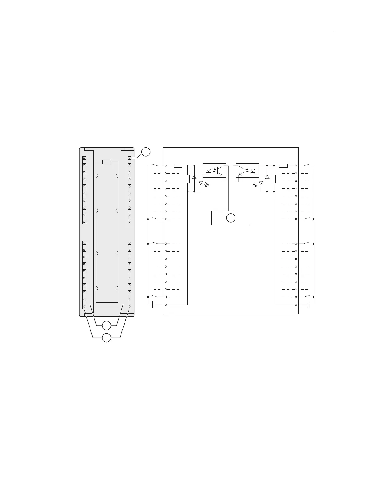
Wiring and block diagram of the DI 32 x DC 24 V

9






0
0
9















0
0
6)
Channel number
Status display - green
Backplane bus interface
Group error display - red (SF LED)
ET 200PA SMART I/O modules
10.2 Digital input modules
ET 200PA SMART
126 Operating Instructions, 06/2019, A5E34192013-AB

Table of Contents

Other manuals for Siemens SIMATIC PCS 7

Questions and Answers:

Question and Answer IconNeed help?

Do you have a question about the Siemens SIMATIC PCS 7 and is the answer not in the manual?

Siemens SIMATIC PCS 7 Specifications

General IconGeneral
BrandSiemens
ModelSIMATIC PCS 7
CategoryControl Systems
LanguageEnglish

Related product manuals