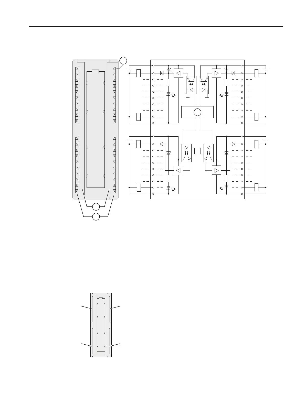
Wiring and block diagram of the DO 32 x DC 24 V/ 0.5 A
9
0
/
0
0
/
9
0
9
/
0
0
0
/
9
0
6)
① Channel number
② Status display - green
③ Backplane bus interface
④ Group error display - red (SF LED)
Terminal assignment
The figure below shows the assignment of the channels to the addresses (output byte x to
output byte x+3).
ET 200PA SMART I/O modules
10.3 Digital output modules
ET 200PA SMART
Operating Instructions, 06/2019, A5E34192013-AB 139
 Loading...


