The 2-wire transducer converts the measured variable to a current. The 2-wire transducers
must be isolated measuring sensors.
Through the use of L+, M for common supply of the transducers, the permitted potential
difference between the channels is revoked. UISO therefore does not apply in the case of 2-
wire transducers.
You can also use a 4-wire transducer with separate supply. This is shown in the figure below
using channel 5 as an example.
6)
0
/
6)
˩3
$'8
:LUH
:LUH
9
[
0
&+
0
/
0
0
&+
0
&+
0
0
0
&+
0
0
0
0
&+
0
0
&+
0
0
&+
0
0
&+
0
0
8Y
8Y
0
1
(OHFWULFDO
LVRODWLRQ
/RJLFDQG
EDFN
SODQHEXV
LQWHUIDFH
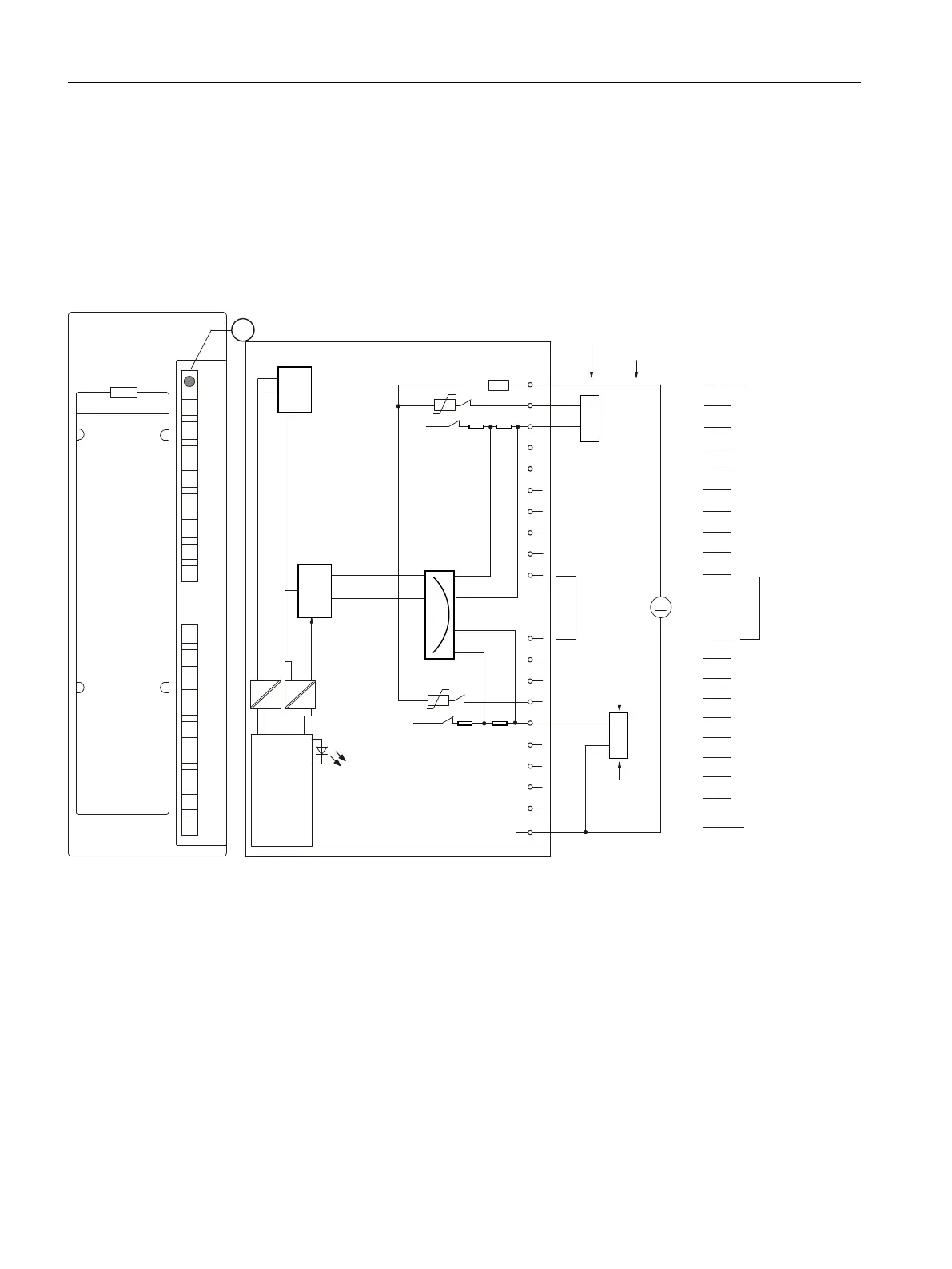
ZLUHWUDQVGXFHU
6KRUWFLUFXLWSURWHFWLRQ
7UDQVGXFHUV
ZLUHWUDQVGXFHU
+DUGZDUHVHWWLQJIRURSHUDWLRQZLWK
ZLUHWUDQVGXFHU
0HDVXULQJ
PXOWLSOH[HU
① Group error display - red (SF LED)
Figure 10-9 Module view and block diagram of the AI 8 x 16 Bit in 2-wire transducer mode
Wiring diagram
When the module is used for 4-wire transducer operation, terminals 10 and 11 must not be
jumpered.
All channels of the module operate in 4-wire transducer mode in this case. Shown using
channel 1 as an example.
ET 200PA SMART I/O modules
10.4 Analog input modules
ET 200PA SMART
166 Operating Instructions, 06/2019, A5E34192013-AB
 Loading...


