Structure of the identifier-related diagnostics
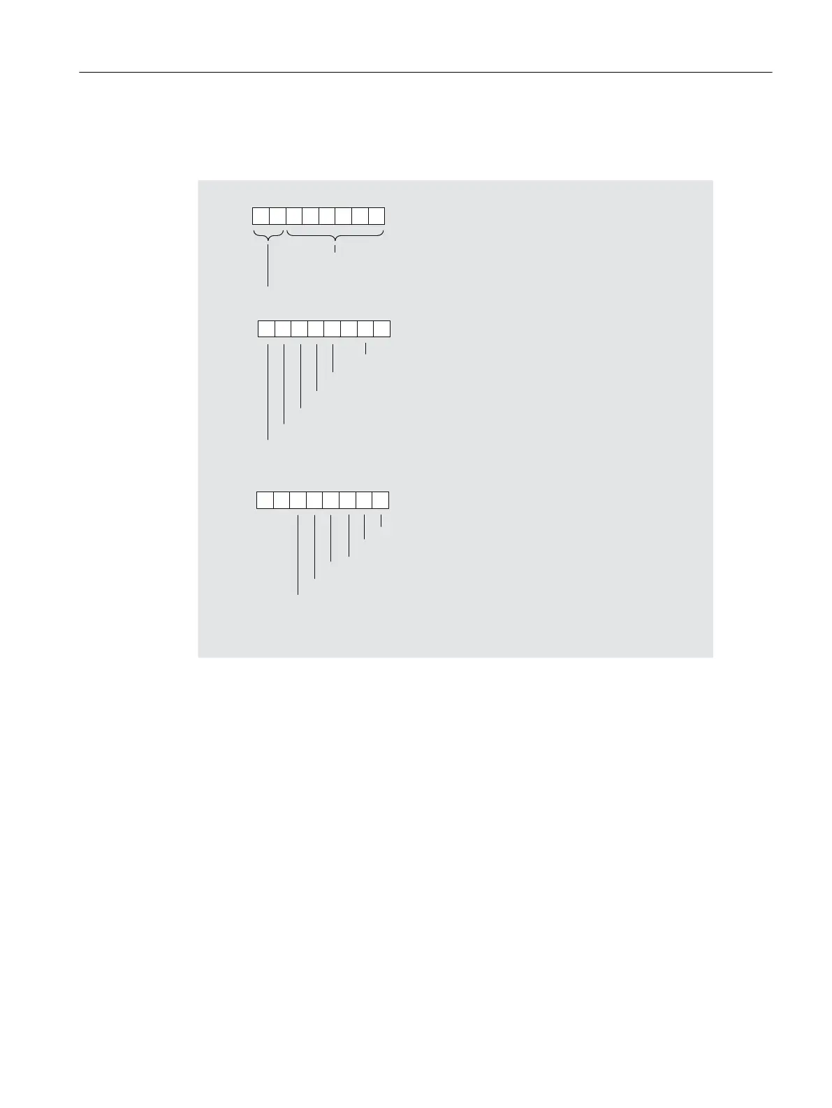
The identifier-related diagnostics for ET 200PA SMART is structured as follows:
%\WH
%\WH
%\WH
%LWQR
/HQJWKRIWKHLGHQWLILHUUHODWHGGLDJQRVWLFV
LQFOXGLQJE\WH E\WHV
&RGHIRULGHQWLILHUUHODWHGGLDJQRVWLFV
(QWU\IRU,0b
(QWU\IRUPRGXOHLQVORW
(QWU\IRUPRGXOHLQVORW
(QWU\IRUPRGXOHLQVORW
(QWU\IRUPRGXOHLQVORW
(QWU\IRUPRGXOHLQVORW
%LWQR
%LWQR
(QWU\IRUPRGXOHLQVORW
(QWU\IRUPRGXOHLQVORW
(QWU\IRUPRGXOHLQVORW
(QWU\IRUPRGXOHLQVORW
(QWU\IRUPRGXOHLQVORW
(QWU\IRUPRGXOHLQVORW
Figure 8-3 Structure of the identifier-related diagnostics
The entry for a module at slot x is set if:
● The module is pulled
● A non-configured module is plugged
● An inserted module cannot be accessed
● The modules signals a diagnostic interrupt
● The ET 200PA SMART is not configured with active bus elements although "Module
replacement in runtime" is enabled in the configuration. In this case, the IM 650 sets the bit
for all modules of the station.
Interrupt, error and system messages
8.3 S7 diagnostics
ET 200PA SMART
Operating Instructions, 06/2019, A5E34192013-AB 97
 Loading...


