Home
Siemens
Controller
SIMATIC S7-1500T
Siemens SIMATIC S7-1500T System Manual
4
of 1
of 1 rating
523 pages
Give review
Manual
Specs
To Next Page
To Next Page
To Previous Page
To Previous Page
Loading...
Commissi
oning
12.4
Operating and system states
S7
-
150
0R/H re
dunda
nt syst
em
System M
anual
,
01/
2024
,
A5E4181
4787
-
AF
401
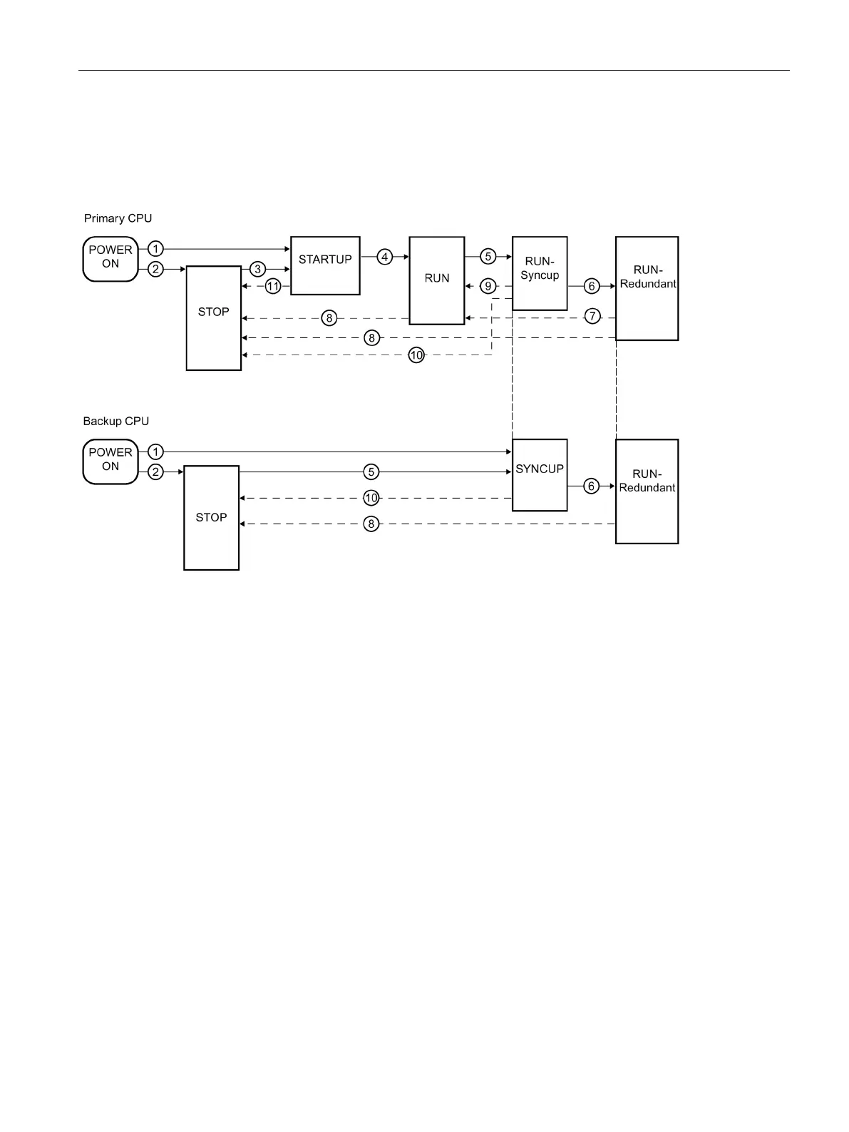
Operating sta
te transitions
Operating state trans
itions of the red
undant system
The following f
igure shows the operating state trans
itions
of the primary and backup CP
U.
Figure
12
-
10
Op
erating state tr
ansitions
401
403
Table of Contents
Table of Contents
4
Introduction
12
S7-1500R/H Documentation Guide
14
Information Classes S7-1500R/H
14
SIMATIC Technical Documentation
15
Safety Information
18
Warnings in this Document
18
Safety-Related Symbols
18
Devices Without Explosion Protection
18
Devices with Explosion Protection
19
Intended Use
20
Changes to the Device and Spare Parts
20
Target Group and Personnel Qualifications
21
Personal Protective Equipment
21
Open Source Software
22
Safe Working
23
Working on Electrical Parts
23
Residual Risks
23
Live Parts
23
Conductive Pollution
24
Laser Radiation
24
Overheating
25
Unsafe Operating States
25
Behavior in Case of Emergency
26
Material Damage
26
Transport and Storage
26
Installation and Connection
26
New Properties/Functions
27
Industrial Cybersecurity
36
Cybersecurity Information
36
Security Update Notification
37
Basic Information on Industrial Cybersecurity
37
Definition of Industrial Cybersecurity
37
Objectives of Industrial Cybersecurity
38
Integrated Security Concept and Security Strategies
38
Comprehensive Security Concept "Defense in Depth
38
Security Management
39
Operational Application Environment and Security Assumptions
41
Intended Use
41
Requirements for the Operational Application Environment and Security Assumptions
42
Security Properties of the Devices
43
Secure Operation of the System
43
Hardening Measures
43
Secure Configuration
44
Access Control
44
Handling of Sensitive Data
44
Regular Firmware Updates
45
Notifications about Security Vulnerabilities (Siemens Security Advisories)
45
Data Backup
46
Security Checks
46
Secure Decommissioning
46
Securely Removing Data
47
Recycling and Disposal
48
Secure Operation of the Engineering Software
49
Secure Operation of Cpus
49
Secure Configuration
49
User Management and Access Control
49
Administration of User Accounts
49
Assigning Secure Passwords
50
Password Management
50
Setting Protection Levels
51
Certificate Management
51
Protection Functions
51
Web API of the Web Server
51
Secure Communication/Opc UA
52
Sensitive Data
52
Backups and Data Backups
52
Additional Protective Measures for Network Security
53
Remote Access to CPU
53
Using a Web Server
53
Recording Security Events
53
Syslog Messages
54
Transfer the Syslog Messages to a Syslog Server
57
Structure of the Syslog Messages
60
Secure Operation of I/O Modules
63
Secure Operation of the Power Supply Modules
63
System Overview
64
What Is the S7-1500R/H Redundant System
64
Areas of Application
65
Operating Principle of the S7-1500R/H Redundant System
69
Plant Components and Automation Levels
80
Scalability
81
Overview of Features
85
Configuration
86
Structure of the S7-1500R Redundant System
86
Structure of the S7-1500H Redundant System
87
Configuration of a Fail-Safe System with SIMATIC S7-1500HF
88
Configuration with Communications Processors
90
Configuration with PROFIBUS DP Connection
93
Components
94
S7-1500 R/H-Cpus
96
Overview of the CPU Technical Specifications
97
Redundancy
98
Safety
107
Security
110
Diagnostics
112
Trace
114
PID Control
116
Communication
119
System and Device IP Addresses
119
Integrated Interfaces for Communication
122
HMI Devices
123
Communications Processor CP1543-1
123
Ie/Pb Link Ha
124
Power Supply
125
Software
127
TIA Portal
127
Sinetplan
128
Proneta
128
SIMATIC Automation Tool
128
Application Planning
130
Requirements
130
Restrictions Compared to the S7-1500 Automation System
133
Configuration Versions
135
S7-1500R/H Configuration with IO Devices in the PROFINET Ring
136
Configuration of S7-1500R/H with Switches and Additional Line Topology
137
Configuration with Communications Processors on Industrial Ethernet
140
Configuration with Communications Processors on Redundant Industrial Ethernet
142
Configuration with Communications Processors and System Power/Load Current Supply
145
Configuration with IE/PB LINK HA
148
Specific Configuration Variants for S7-1500H
151
Configuration of Line Topology with S2 Devices and Switch
151
Configuration of PROFINET Rings with R1 Devices
153
Configuration of PROFINET Rings with R1 Devices and Switches with MRP Interconnection
157
Configuration of PROFINET Rings with R1 Devices and Y-Switch with S2 Devices
159
Configuration of Line Topology with R1 Devices
162
Line Topology Configuration with R1 Devices and Switches
164
Line Topology Configuration with R1 Devices and Y-Switch with S2 Devices
166
Configuration of Combined Topology with S2 Devices
169
Configuration of Combined Topology with R1 Devices
170
Configuration Without Additional Devices
172
Redundancy Scenarios
173
Introduction
173
Failure of the Primary CPU
174
Failure of the Backup CPU
176
Failure of the PROFINET Cable in the PROFINET Ring
178
Failure of the Primary CPU with Communications Processor
180
Specific Redundancy Scenarios for S7-1500R
181
Failure of a Communications Processor at the Primary CPU
181
Specific Redundancy Scenarios for S7-1500H
182
Failure of a Redundancy Connection in S7-1500H
182
Failure of both Redundancy Connections in S7-1500H > 55 Ms Apart
184
Failure of both Redundancy Connections and the PROFINET Cable in the PROFINET Ring
186
Failure of the Two PROFINET Cables in the PROFINET Ring on the Backup CPU
189
Failure of an Interface Module in an R1 Device in a PROFINET Ring
191
Failure of the Two PROFINET Lines in PROFINET Ring 1 at the Primary CPU with R1 Devices
193
Failure of both PROFINET Lines between Two R1 Devices in a Line Topology
195
Failure of a PROFINET Line between Two S2 Devices in a Line Topology
197
Failure of a Communications Processor at the Primary CPU
198
Failure Scenarios
199
Failure of an IO Device in the PROFINET Ring
200
Failure of a Switch (with Additional Line Topology) in the PROFINET Ring
201
Specific Failure Scenarios with S7-1500R
203
Two Cable Interruptions in the PROFINET Ring in S7-1500R > 1500 Ms Apart
203
Two Cable Interruptions in the PROFINET Ring in S7-1500R Within ≤ 1500 Ms
205
Failure of the Primary CPU When IO Devices Have Failed in the PROFINET Ring
207
Failure of the Backup CPU and Failure of the CP Communications Processor at the Primary CPU
209
Specific Failure Scenarios with S7-1500H
211
Failure of both Redundancy Connections in S7-1500H ≤ 55 Ms Apart
211
Failure of One Redundancy Connection and the Primary CPU in S7-1500H
214
Failure of the Two PROFINET Cables in the PROFINET Ring at the Primary CPU
215
Failure of the Redundant System through Safe State of the HF-Cpus
217
Failure of an Interface Module in an R1 Device and of the PROFINET Lines in Two Places of a PROFINET Ring
219
Failure of the Primary CPU in PROFINET Rings with R1, S2 and S1 Devices
221
Failure of PROFINET Lines in Two Places in a Line Topology with S2 Devices
223
Failure of the Communications Processor at the Primary CPU with Failure of the Backup CPU
225
Hardware Configuration
227
Using HMI Devices
229
System Power Supply
232
Use of System Power Supplies
232
Power Balance Calculation
235
Installation
239
Basics
239
Installing the Mounting Rail
241
Installing the Active Backplane Bus
245
Installing the Standard Rail Adapter
245
Installing a System Power Supply
251
Installing a Load Current Supply
253
Installing R/H-Cpus
254
Installing a Communications Processor
256
Wiring
259
Rules and Regulations for Operation
259
Operation on Grounded Infeed
261
Electrical Configuration
265
Wiring Rules
266
Connecting the Supply Voltage
267
Connecting the System Power/Load Current Supply
269
Connecting the CPU to the Load Power Supply
270
Connecting Interfaces for Communication with S7-1500R
272
Connecting the PROFINET Ring to S7-1500
272
Connecting Interfaces for Communication with S7-1500H
274
Connecting Redundancy Connections (Fiber-Optic Cables)
275
Synchronization Modules for S7-1500H
275
Selecting Fiber-Optic Cables
275
Installing Fiber-Optic Cables
278
Connecting Redundancy Connections (Fiber-Optic Cables) to S7-1500H
280
Connecting the PROFINET Ring to S7-1500H
284
Connecting Line Topology to S7-1500H
287
Connecting a Communications Processor
289
Configuration
290
Requirements
290
Configuring R/H Cpus
290
Basic Procedure for Configuring the IO Devices and the MRP Roles
294
Configuring H-Cpus with PROFINET Rings and R1 Devices
298
Configuring Additional Topologies
303
Configuring R-Cpus with Communications Processors
305
Configuring the System Power Supply
307
Configuring the IE/PB LINK HA
309
Display of the IO Device Assignments in STEP 7
311
Project Tree
314
Parameters
315
Process Images and Process Image Partitions
315
Process Image - Overview
315
Updating Process Image Partitions in the User Program
316
Basics of Program Execution
318
Programming the S7-1500R/H
318
Restrictions
322
Events and Obs
324
Special Instructions for S7-1500R/H Redundant Systems
330
Disabling/Enabling SYNCUP with the RH_CTRL Instruction
330
Determining the Primary CPU with "Rh_Getprimaryid
333
Asynchronous Instructions
334
Protection
342
Overview of the Protection Functions
342
Protection of Confidential Configuration Data
342
Local User Management
343
Useful Information on the Local User Administration and Access Control
343
Advantages of the Local User Administration and Access Control
346
From the Access Level to the Function Right of Users
348
Information about Compatibility
351
Configuring Access Protection for the CPU
351
Using the Display to Set Additional Password Protection
355
Using the User Program to Set Additional Access Protection
355
Know-How Protection
356
Protection by Locking the CPU
360
Commissioning
361
Overview
361
12.2 Check before Powering on for the First Time
362
Commissioning Procedure
363
Removing/Plugging in SIMATIC Memory Cards
364
First Power-On of the Cpus
367
CPU Pairing
367
Redundancy Ids
369
Downloading Projects to the Cpus
373
Operating and System States
381
Overview
381
STARTUP Operating State
384
STOP Operating State
387
SYNCUP Operating State
388
RUN Operating States
388
SYNCUP System State
389
System and Operating State Transitions
401
Loss of Redundancy CPU
412
Displaying and Changing the System State
416
CPU Memory Reset
418
Automatic Memory Reset
419
Manual Memory Reset
420
Backing up and Restoring the CPU Configuration
422
Time Synchronization
426
Example: Configuring the NTP Server
427
Identification and Maintenance Data
428
Reading out and Entering I&M Data
428
Record Structure for I&M Data
430
Example: Read out Firmware Version of the CPU with Get_Im_Data
432
Display
435
CPU Display
435
Maintenance
444
Replacing Components of the S7-1500R/H Redundant System
444
Checking before Replacing Components
444
Replacing Defective R/H-Cpus
447
Replacing Defective Redundancy Connections
448
Replacing Two Defective PROFINET Cables with S7-1500R
449
Replacing a Defective Redundancy Connection with S7-1500H
450
Replacing Defective Synchronization Module with S7-1500H
451
Replacing both Defective Redundancy Connections with S7-1500H
451
Replacing Defective PROFINET Cables
452
Replacing a Defective SIMATIC Memory Card
453
Replacing a Defective System Power/Load Current Supply
454
Replacing a Defective Communications Processor
455
Replacing Defective IO Devices/Switches
456
Replacing the Display
457
Replacing the Coding Element at the Power Connector of the System Power/Load Current Supply
460
Firmware Update
462
Resetting Cpus to Factory Settings
467
Maintenance and Repair
471
Test and Service Functions
472
Test Functions
472
Reading Out/Saving Service Data
478
Technical Specifications
480
Standards and Approvals
480
Electromagnetic Compatibility
488
Shipping and Storage Conditions
491
Mechanical and Climatic Ambient Conditions
491
Information on Insulation Tests, Protection Class, Degree of Protection and Rated Voltage
493
Use of S7-1500R/H in Zone 2 Hazardous Area
494
Dimension Drawings
495
Accessories/Spare Parts
498
Use over 2 000 M above Sea Level and Extended Temperature Range
500
Ambient Temperature and Installation Altitude
500
Cpus
500
Restrictions
502
Glossary
504
Index
518
Other manuals for Siemens SIMATIC S7-1500T
Manual
188 pages
Operating Instructions
103 pages
Safety Programming Guideline
48 pages
Function Manual
527 pages
Getting Started
126 pages
Application Description
50 pages
Reference Manual
88 pages
User Manual
83 pages
Configuration Manual
20 pages
Equipment Manual
82 pages
Guide
15 pages
4
Based on 1 rating
Ask a question
Give review
Questions and Answers:
Need help?
Do you have a question about the Siemens SIMATIC S7-1500T and is the answer not in the manual?
Ask a question
Siemens SIMATIC S7-1500T Specifications
General
Brand
Siemens
Model
SIMATIC S7-1500T
Category
Controller
Language
English
Related product manuals
Siemens Simatic S7-1500
188 pages
Siemens Simatic S7-1500R
45 pages
Siemens Simatic S7-1500H
45 pages
SIMATIC S7-1500 Automation System
208 pages
Siemens SIMATIC S7-1200
364 pages
SIMATIC NET TeleControl S7-1200 CP 1243-1
112 pages
Siemens SIMATIC S7
336 pages
Siemens Simatic S7-300
594 pages
Siemens Simatic S7 Series
75 pages
Siemens SIMATIC S7-300 Series
192 pages
Siemens Simatic S7-200 CPU 210
140 pages
SIMATIC S7-300 Module data
594 pages
 Loading...


