Maintenance
14.2 Replacing the display/front cover
S7-1500R/H redundant system
458 System Manual, 01/2024, A5E41814787-AF
Replace front cover (R/H-CPUs with article numbers 6ES7513-1RL00-0AB0, 6ES7515-2RM00-0AB0,
6ES7517-3HP00-0AB0, 6ES7518-4JP00-0AB0)
To remove the front cover from the CPU, follow these steps:
1. Flip up the front cover until the front cover stands at a 90° angle to the front of the module.
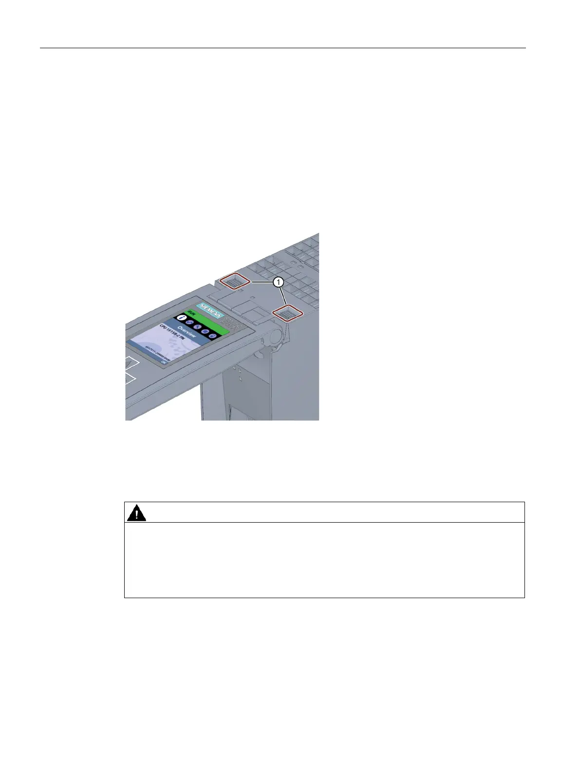
2. In the top section of the front cover, press on the anchor(s): Two anchors with
CPU 1515R-2 PN, CPU 1517H-3 PN and CPU 1518HF-4 PN. One anchor with
CPU 1513R-1 PN.
At the same time, pull the front cover towards you and off.
The view in the figure below is an example of CPU 1515R-2 PN.
Fasteners for removing and fitting the front panel
Figure 14-3 Remove display
Zone 2 hazardous area
Personal injury or material damage can occur in zone 2 hazardous areas
If you remove or attach the front cover/display during operation, personal injury and
damage can occur in hazardous areas of zone 2.
Always disconnect the R/H-CPU from the power supply before you remove or attach the
front cover in hazardous areas of zone 2.
 Loading...


