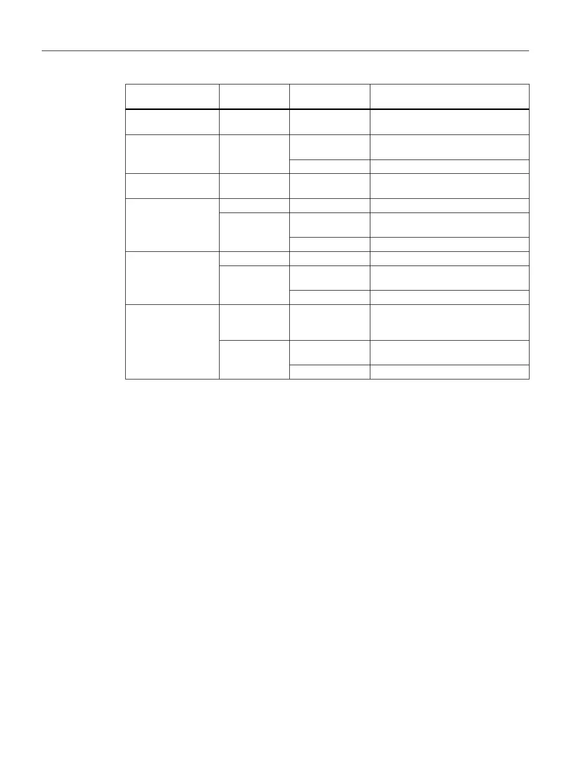
Diagnostic message "Diagnostics"
parameter
"Reaction to Error"
parameter
Input value of digital module
Incorrect parameters
(module/channel)
Cannot be disa‐
bled
Not relevant 0 signal (module/all incorrectly config‐
ured channels)
Internal voltage failure Cannot be disa‐
bled
Substitute a value
(SV)
Configured substitute value
KLV Last read, valid value
Hardware interrupt
lost
Cannot be disa‐
bled
Not relevant Current process value
Wire break (for each
channel)
Disabled - 0 signal
Activated Substitute a value
(SV)
Configured substitute value
KLV Last read, valid value
Sensor supply miss‐
ing (also activated via
"No Load Voltage L+")
Disabled - 0 signal
Activated Substitute a value
(SV)
Configured substitute value
KLV Last read, valid value
No load voltage L+
(for each channel
group)
Disabled - 0 signal, if the contact is connected via
the sensor supply; process value for
the external sensor supply
Activated Substitute a value
(SV)
Configured substitute value
KLV Last read, valid value
Behavior when the input delay equals 0.1 ms or 0.05 ms and an error occurs
If you have set the following parameters:
● Input delay: 0.1 ms or 0.05 ms
● Reaction to error: "Keep Last Value" (KLV) or "Substitute Value" (SV)
● Set substitution value "1"
In the event of a fault on a channel that has a 1 signal, the following could occur:
● A 0 signal may be briefly output
● If configured, a hardware interrupt may be generated.
This occurs before the last valid value or substitute value "1" is output.
Digital modules
4.8 Digital input module SM 421; DI 16 x DC 24 V (6ES7421-7BH01-0AB0)
S7-400 Automation System Module Data
108 Reference Manual, Ausgabe 11/2016, A5E00850736-08

 Loading...


