5.25.2 Commissioning the SM 431; AI 8 x 16 Bit
Setting the operating mode
You set the operating mode of the SM 431; AI 8 x16 Bit in STEP 7.
Parameters
You will find a description of the general procedure for assigning parameters to analog modules
in the respective sections.
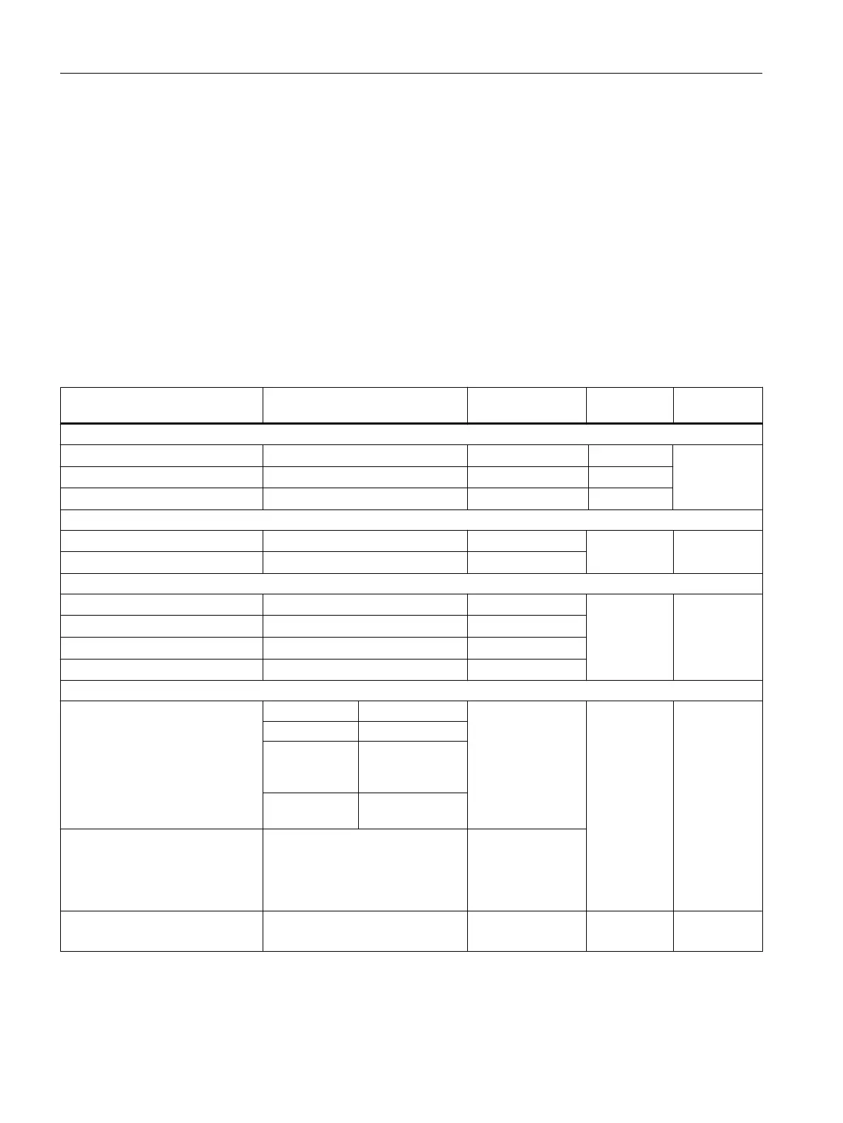
The table below provides an overview of configurable parameters, including defaults.
Table 5-71 Parameters of the SM 431; AI 8 x 16 Bit
Parameters Value range Default
2
Parameter
type
Scope
Enable
● Diagnostic interrupt
1
Yes/no No Dynamic Module
● Hardware interrupt
1
Yes/no No Dynamic
● Destination CPU for interrupt
1 to 4 - Static
Trigger for hardware interrupt
3)
● High limit
32767 to - 32768 - Dynamic Channel
● Low limit
- 32768 to 32767 -
Diagnostics
● Wire break
Yes/no No Static Channel
● Reference channel error
Yes/no No
● Underflow
Yes/no No
● Overflow
Yes/no No
Measurement
● Measuring method
Disabled TC-L Static Channel
U Voltage
4DMU Current
(4-wire transduc‐
er)
TC-L Thermocouple
(linear)
● Measuring range
For information on configurable
measuring ranges of input chan‐
nels, refer to the section "Measur‐
ing methods and measuring rang‐
es of SM 431, AI 8 x 16 Bit".
Type J
● Reference temperature
- 273.15 to 327.67
o
C
-327.68 to 327.67
o
C
100
o
C Dynamic Module
Analog modules
5.25 Analog input module SM 431; AI 8 x 16 Bit (6ES7431-7KF00-0AB0)
S7-400 Automation System Module Data
310 Reference Manual, Ausgabe 11/2016, A5E00850736-08

 Loading...


