5.10 Connecting voltage sensors
Connecting voltage sensors
Note
The cables required to connect the analog input module and the sensors are not drawn in the
figures shown below.
In other words, you must continue to read and follow the instructions in the section "Connecting
sensors to analog inputs", which contains general information on connecting sensors.
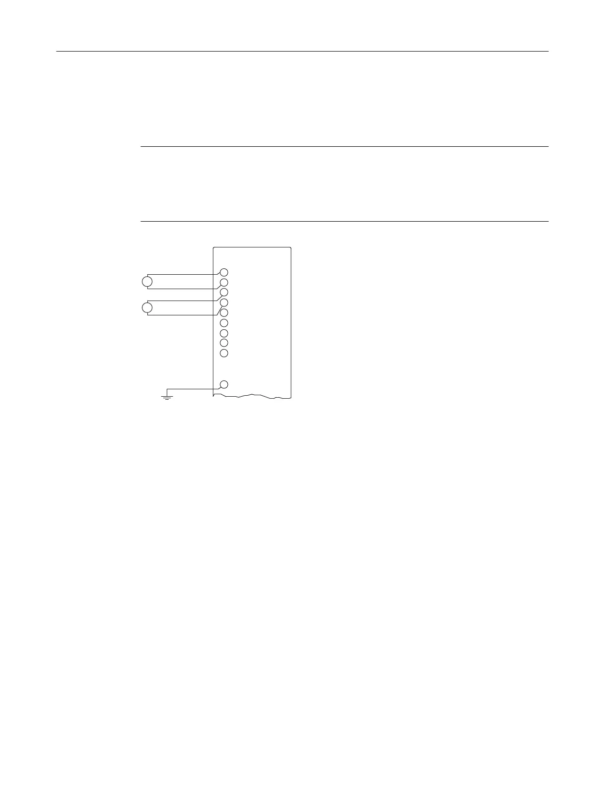
Figure 5-7 Connecting voltage sensors to an AI
M +: Measuring line (positive)
M -: Measuring line (negative)
M
ANA
: Reference potential of the analog measuring circuit
(1) Connection required for modules with M
ana
Analog modules
5.10 Connecting voltage sensors
S7-400 Automation System Module Data
Reference Manual, Ausgabe 11/2016, A5E00850736-08 207

 Loading...


