9.5 The 24 V DC fan subassembly (6ES7408-1TA01-0XA0)
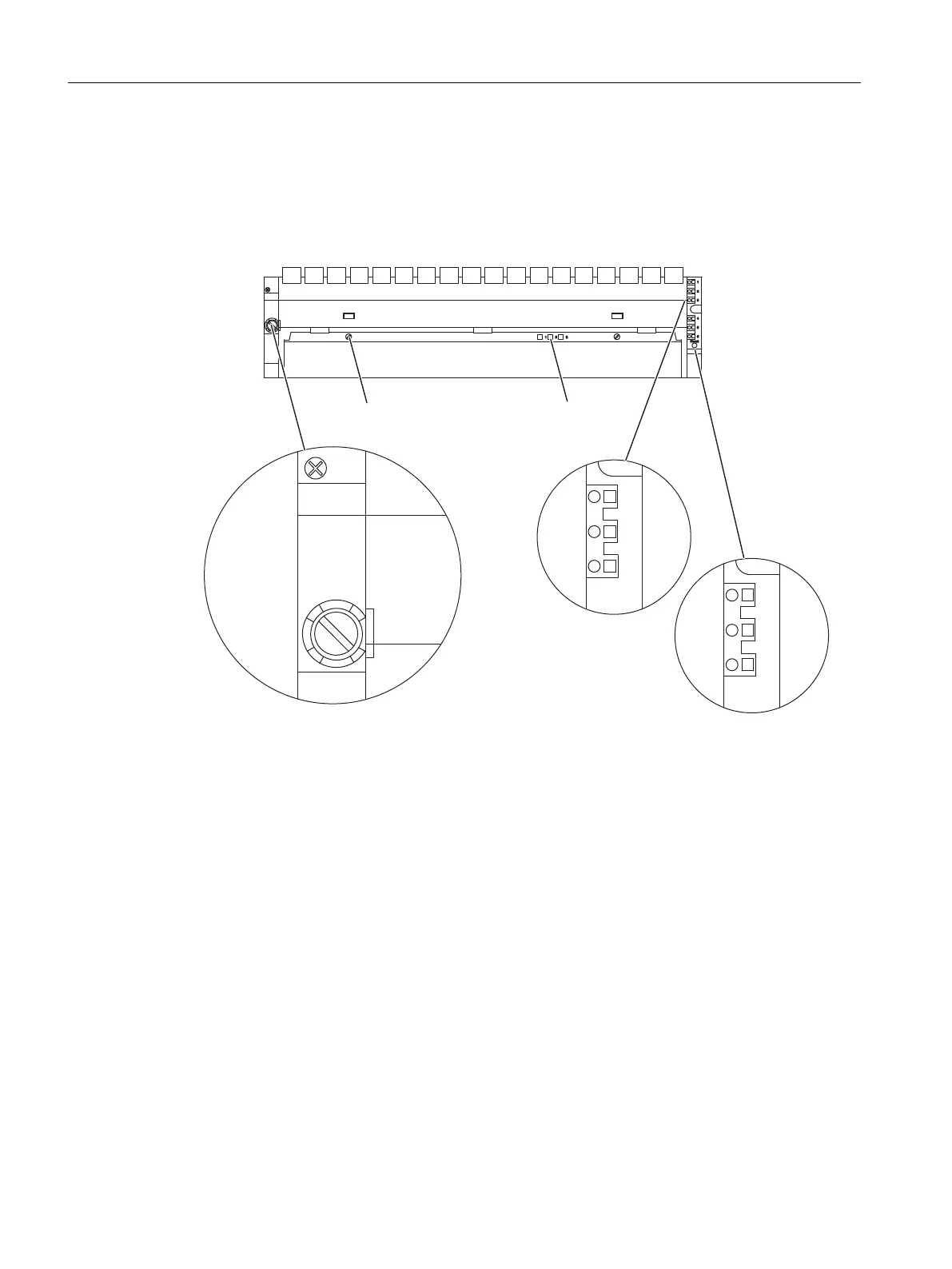
Operator controls and indicators on the 24 VDC fan subassembly
1 AT
1, 2, 3
4, 5, 6
1 AT
Quick-release lock LEDs F1, F2, F3
Relay contact
Relay contact
Fuse
case
Figure 9-4 Controls and indicators of the fan subassembly 24 VDC (6ES7408-1TA00-0XA0)
Features
The 24 VDC fan subassembly has the same construction and functional characteristics as the
120/230 VAC fan subassembly.
Wiring
You connect the 24 VDC fan subassembly to the 24 VDC supply in the same manner as for
the 120/230 VAC fan subassembly. You should note the polarity of the spring connections L+
and L-.
Signaling concept
The signaling concept of the 24 VDC fan subassembly is identical to the signaling concept of
the 120/230 VAC fan subassembly.
Cable duct and fan subassemblies
9.5 The 24 V DC fan subassembly (6ES7408-1TA01-0XA0)
S7-400 Automation System Module Data
384 Reference Manual, Ausgabe 11/2016, A5E00850736-08

 Loading...


