5.24.2 Commissioning the SM 431; AI 8 x RTD x 16 Bit
Setting the operating mode
You set the operating mode of the SM 431; AI 8 x RTD x 16 Bit in STEP 7.
Parameters
You will find a description of the general procedure for assigning parameters to analog modules
in the respective sections.
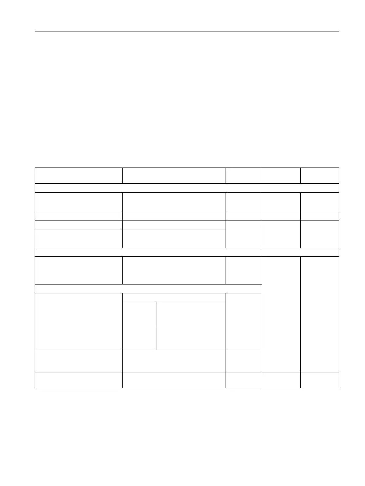
The table below provides an overview of configurable parameters, including defaults.
Table 5-68 Parameters of the SM 431; AI 8 x RTD x 16 Bit
Parameters Value range Default
2
Parameter
type
Scope
Enable
● Diagnostic interrupt
1
● Hardware interrupt
1
Yes/no
Yes/no
No
No
Dynamic Module
● Destination CPU for interrupt
1 to 4 - Static Module
Trigger for hardware interrupt
3)
- Dynamic Channel
● High limit
● Low limit
32767 to - 32768
- 32768 to 32767
Diagnostics
● Wire break
● Underflow
● Overflow
Yes/no
Yes/no
Yes/no
No
No
No
Static Channel
Measurement
● Measuring method
Disabled RTD-3L
RTD-4L Thermal resistance
(linear, 4-conductor con‐
nection)
RTD-3L Thermal resistance
(linear, 3-conductor con‐
nection)
● Measuring range
Refer to the respective section for the
measuring ranges of the input channels
that you can set.
Pt 100
Standard
● Temperature unit
Degrees Celsius; degrees Fahrenheit Degrees
Celsius
Static Module
Analog modules
5.24 Analog input module SM 431; AI 8 x RTD x 16 Bit (6ES7431-7KF10-0AB0)
S7-400 Automation System Module Data
Reference Manual, Ausgabe 11/2016, A5E00850736-08 299

 Loading...


