5.16 Connecting loads/actuators to current outputs
Connecting loads to current outputs
Always connect loads to Q
I
and to the reference point of analog circuit M
ANA
of a current output.
Note
The cables required to connect the analog output module are not drawn in the figure shown
below.
In other words, you must continue to read and follow the instructions in the section "Connecting
loads/actuators to analog outputs", which contains general information on connecting sensors.
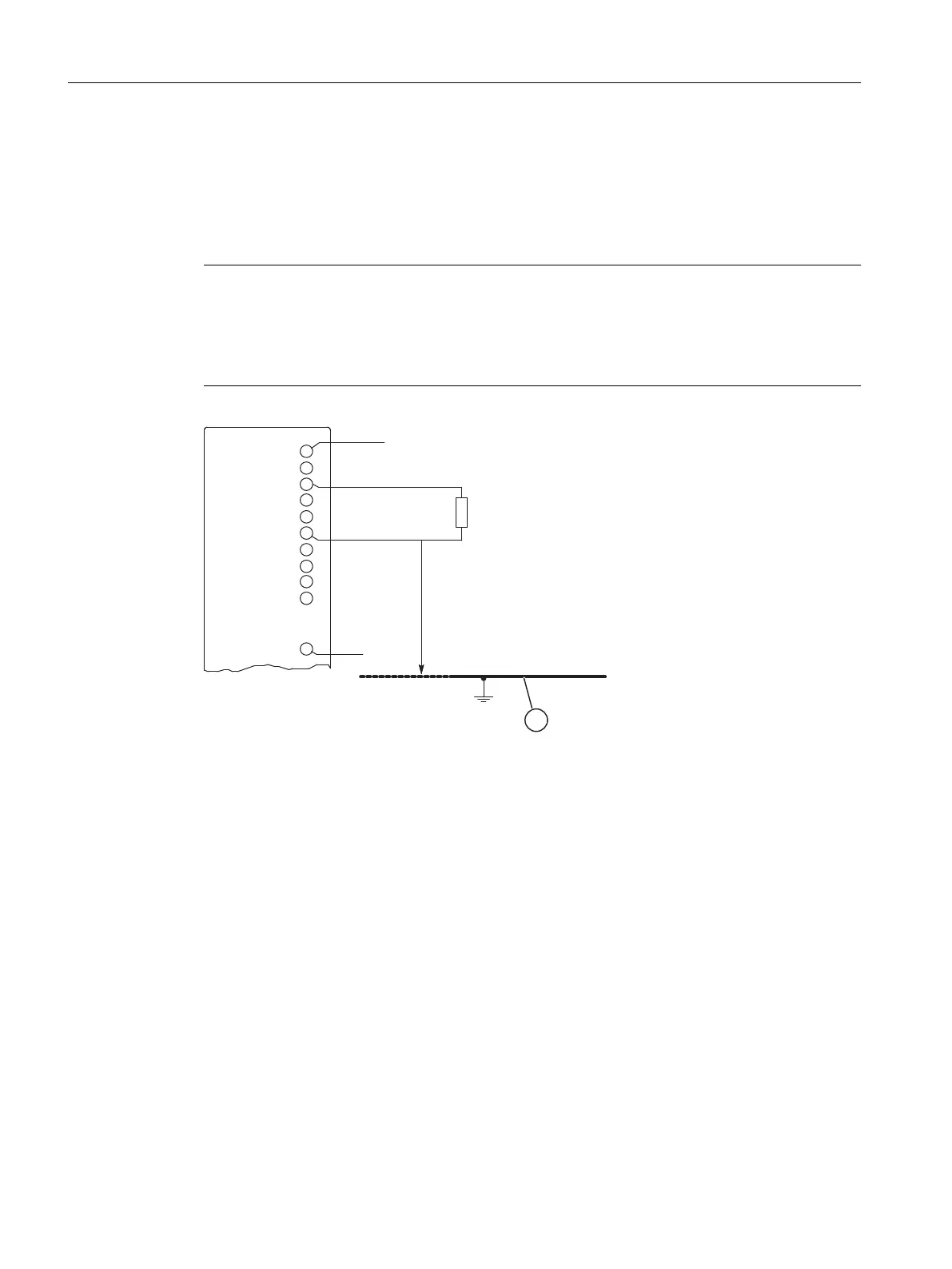
Figure 5-20 Connecting loads to a current output of an isolated AO
L +: Terminal for 24 VDC supply voltage
Q
I
: Analog output current
M
ANA
: Reference potential of the analog circuit
M : Ground
U
ISO
: Potential difference between M
ANA
and chassis ground
(1) Chassis ground
See also
Connecting loads/actuators to analog outputs (Page 219)
Analog modules
5.16 Connecting loads/actuators to current outputs
S7-400 Automation System Module Data
222 Reference Manual, Ausgabe 11/2016, A5E00850736-08

 Loading...


