4.15.2 Assigning parameters to the SM 422; DO 16 x DC 20-125 V/1.5 A
Parameter assignment
You will find a description of the general procedure for assigning parameters to digital modules
in the respective sections.
Parameters of the SM 421; DO 16 x DC 20-125 V/1.5 A
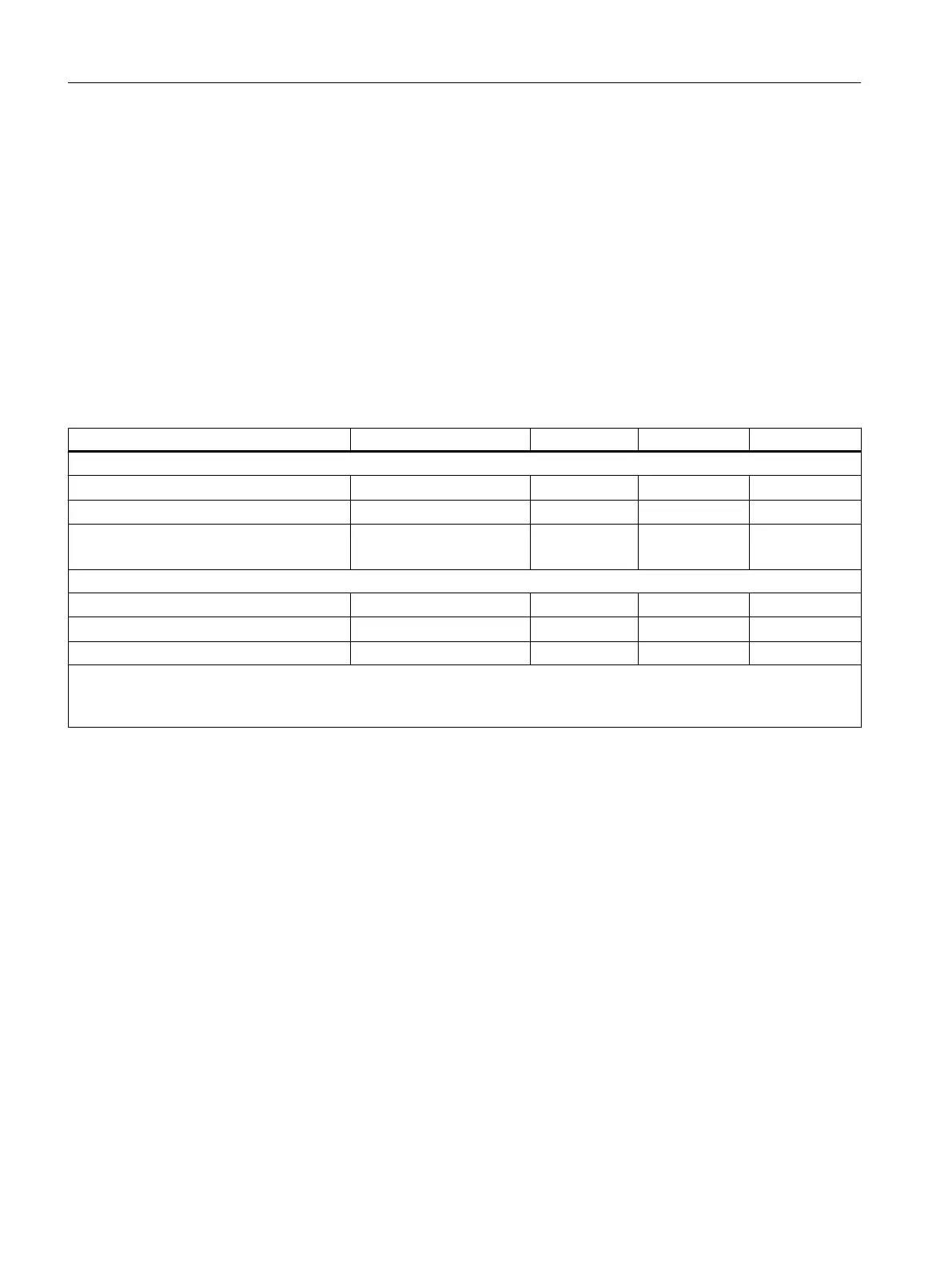
You will find an overview of the parameters you can set and their default settings for the SM
422; DO 16 x DC 20-125 V/1.5 A in the following table.
Table 4-12 Parameters of the SM 421; DO 16 x DC 20-125 V/1.5 A
Parameters Value range Default setting
2
Parameter type Scope
Enable
● Diagnostic interrupt
1
Yes/no No Dynamic Module
● Destination CPU for interrupt
1 to 4 - Static Module
Reaction to CPU STOP Substitute a value (SV)
Keep last value (KLV)
SV Dynamic Module
Diagnostics
● Load voltage L+ missing
Yes/no No Static Channel group
● Short-circuit to M
Yes/no No Static Channel
Set substitution value "1" Yes/no No Dynamic Channel
1
If you use the module in ER-1/ER-2, you must set this parameter to "No" because the interrupt lines are not available in
ER-1/ER-2.
2
Only in the CR (central rack) is it possible to start up the digital modules with the default settings.
Assigning the "No load voltage L+" diagnostics to channel groups
You can only set the "No load voltage L+" diagnostics separately for each channel group. In
other words, the setting for channel 0 applies to inputs 0 to 7, and the setting for channel 8
applies to inputs 8 to 15.
See also
Parameters (Page 85)
Digital modules
4.15 Digital output module SM 422; DO 16 x DC 20-125 V/1.5 A (6ES7422-5EH10-0AB0)
S7-400 Automation System Module Data
136 Reference Manual, Ausgabe 11/2016, A5E00850736-08

 Loading...


