B.4 Diagnostic data of the digital output modules as of byte 2
Overview
The structure and contents of the different bytes of the diagnostic data for special digital output
modules are described below. General rule: When an error occurs, the bit concerned is set to
"1".
You will find a description of possible error causes and appropriate remedies in the section on
the special module.
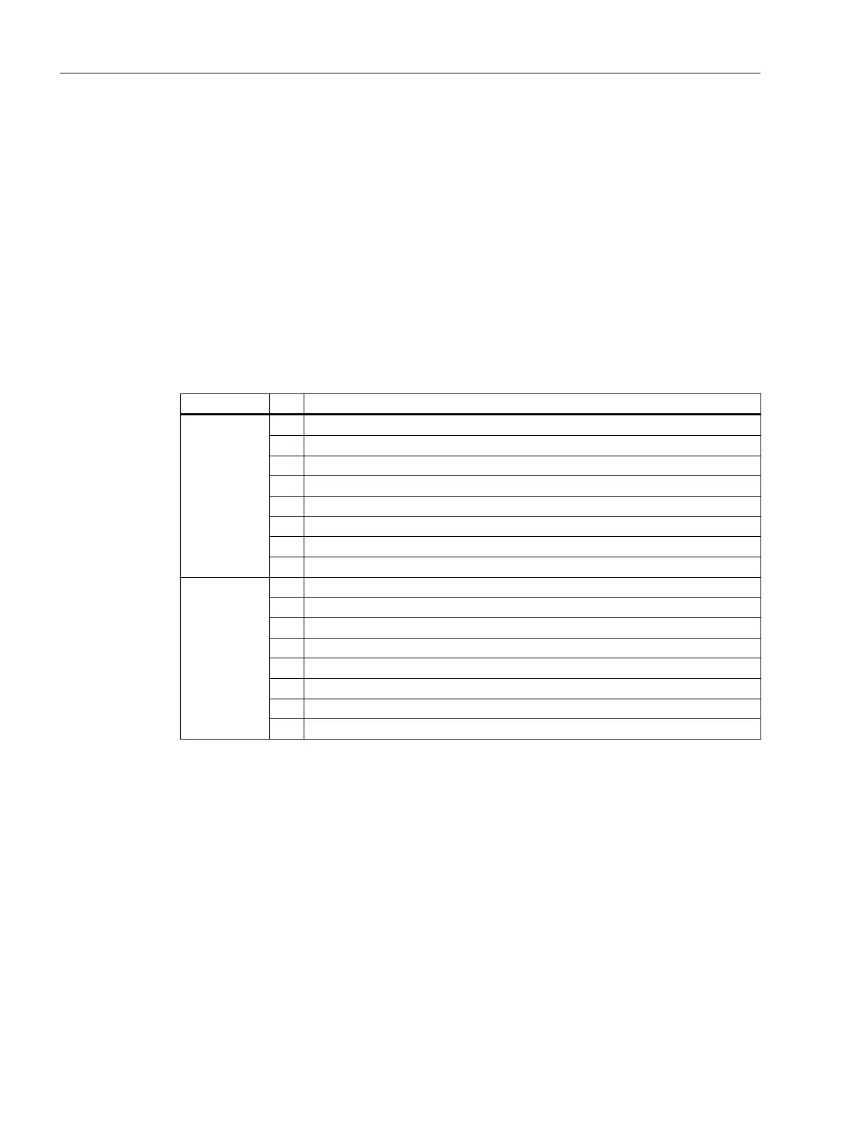
Bytes 2 and 3 of the SM 422; DO 16 x DC 20-125 V/1.5 A
Table B-9 Bytes 2 and 3 of the diagnostic data of the SM 422; DO 16 x DC 20-125 V/1.5 A
Byte Bit Meaning
Byte 2 7 0
6 0
5 0
4 0
3 0
2 Operating mode 0: RUN; 1: STOP
1 0
0 0
Byte 3 7 0
6 0
5 0
4 0
3 0
2 EPROM error
1 0
0 0
Diagnostic data of signal modules
B.4 Diagnostic data of the digital output modules as of byte 2
S7-400 Automation System Module Data
412 Reference Manual, Ausgabe 11/2016, A5E00850736-08

 Loading...


