4.3.3 Parameters of digital output modules
Overview
The configurable digital output modules use a subset of the parameters and ranges of values
listed in the table below, depending on the functionality. For information on subsets "supported"
by specific digital modules, refer to the section dealing with the relevant module beginning with
section 4.7.
The defaults apply if you have not set any parameters in
STEP 7
.
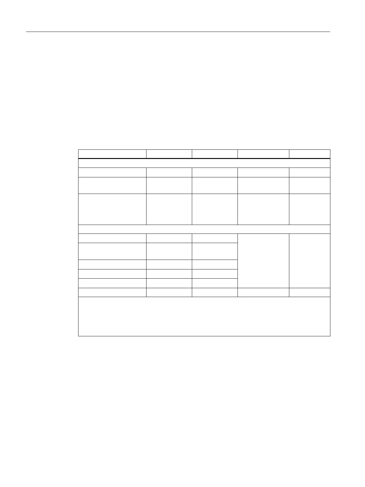
Table 4-5 Parameters of digital output modules
Parameters Value range Default
2
Parameter type Scope
Enable
● Diagnostic interrupt
1
Yes/no No Dynamic Module
● Destination CPU for
interrupt
1 to 4 - Static Module
Reaction to CPU STOP Substitute a val‐
ue (SV)
Keep last value
(KLV)
SV Dynamic Module
Diagnostics
● Wire break
Yes/no No Static Channel
● Load voltage L+
missing
Yes/no No
● Short-circuit to M
Yes/no No
● Short-circuit to L+
Yes/no No
● Fuse blown
Yes/no No
Set substitution value "1" Yes/no No Dynamic Channel
3
1
If you use the module in ER-1/ER-2, you must set this parameter to "No" because the interrupt lines
are not available in ER-1/ER-2.
2
Only in the CR (central rack) is it possible to start up the digital modules with the default settings and
without support from HWCONFIG.
3
Channels not selected for substitute value "1" are assigned substitute value "0".
4.4 Diagnostics for digital modules
4.4.1 General information about diagnostic messages
Programmable and non-programmable diagnostic messages
Using the diagnostics function, we make a distinction between programmable and non-
programmable diagnostic messages.
Digital modules
4.4 Diagnostics for digital modules
S7-400 Automation System Module Data
88 Reference Manual, Ausgabe 11/2016, A5E00850736-08

 Loading...


