B.2 Structure and contents of diagnostic data bytes 0 and 1
Overview
The section below describes the structure and content of the various bytes in diagnostic data.
General rule: When an error occurs, the bit concerned is set to "1".
Bytes 0 and 1
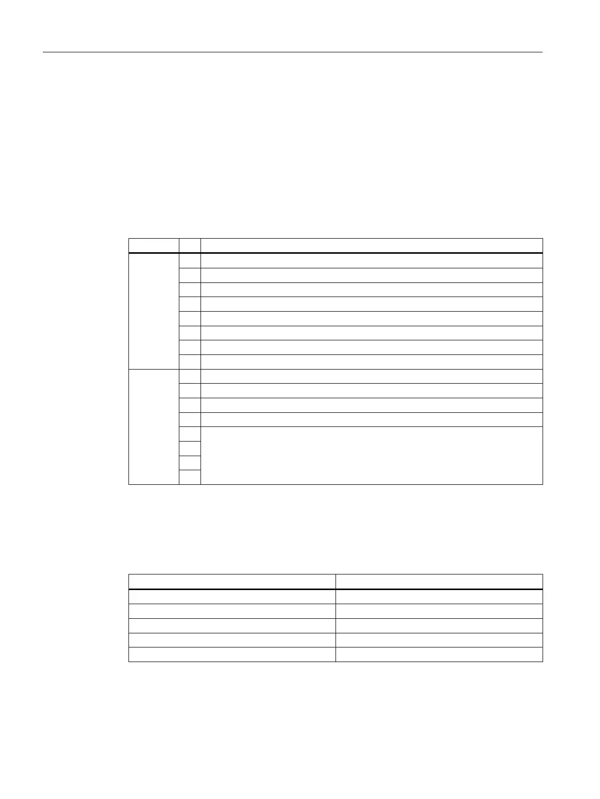
Table B-1 Bytes 0 and 1 of diagnostic data
Byte Bit Meaning
Byte 0 7 Incorrect parameter in the module
6 No module parameters
5 Front connector missing
4 External auxiliary voltage missing
3 Channel error
2 External error
1 Internal error
0 Module error
Byte 1 7 0
6 0
5 0
4 Channel information available
3
Module type (see table "Codes of the module types")
2
1
0
Module types
The table below lists the module type IDs (bits 0 to 3 in byte 1).
Table B-2 Codes of the module types
ID Module type
0101 Analog module
0110 CPU
1000 Function module
1100 CP
1111 Digital module
Diagnostic data of signal modules
B.2 Structure and contents of diagnostic data bytes 0 and 1
S7-400 Automation System Module Data
406 Reference Manual, Ausgabe 11/2016, A5E00850736-08

 Loading...


