5.19 Analog input module SM 431; AI 8 x 13 Bit (6ES7431-1KF00-0AB0)
5.19.1 Features
Overview
The analog input module SM 431; AI 8 x 13 bit has the following features:
● 8 inputs for voltage/current measurement
● 4 inputs for resistance measurement
● Various measuring ranges, adjustable in parallel
● Resolution 13 bits
● Analog section isolated from the CPU
● Maximum permitted common mode voltage between the channels or between the reference
potentials of the connected sensors and M
ANA
30 V AC
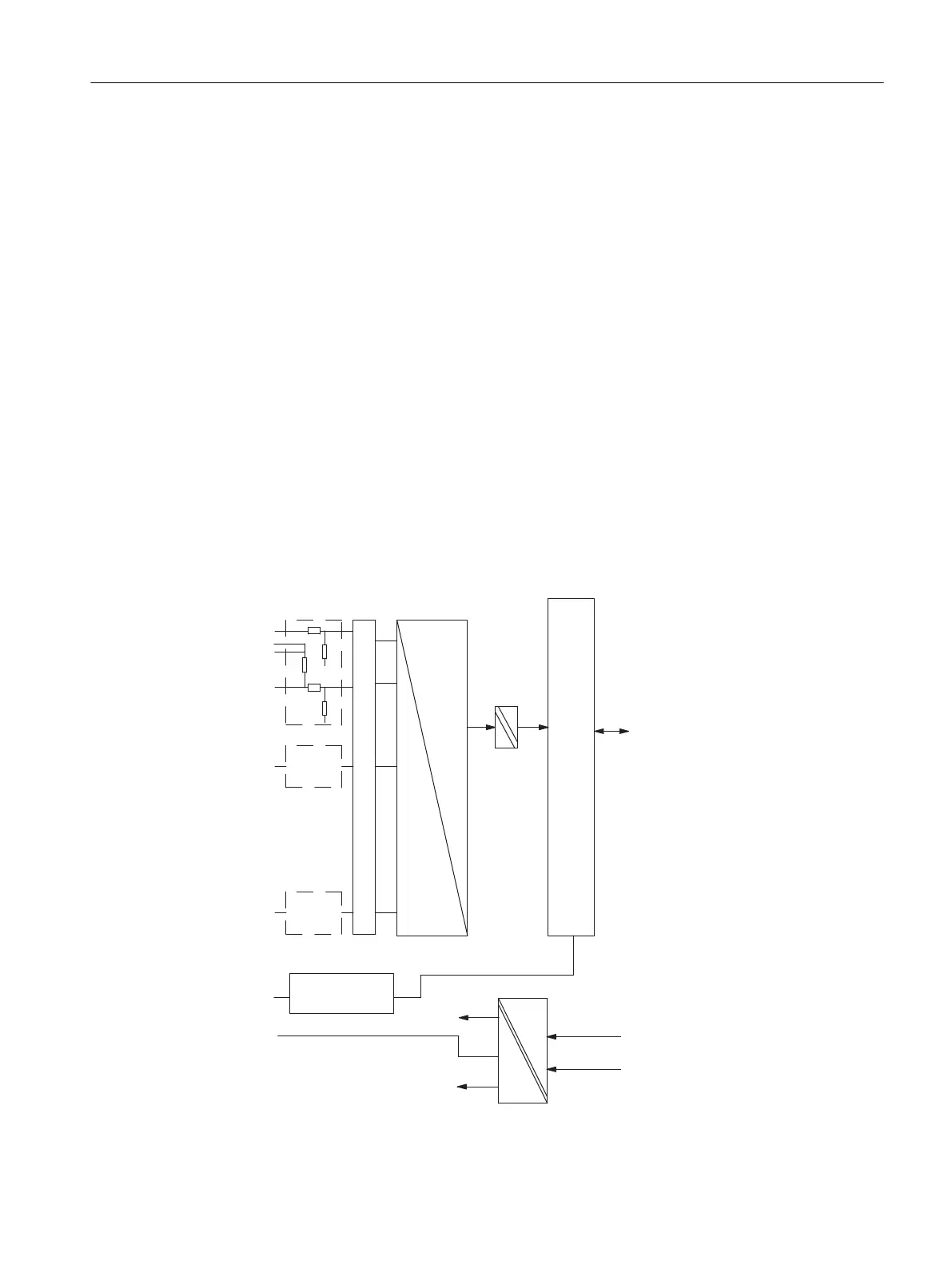
Circuit diagram for SM 431; AI 8 x 13 bit
A
D
+5V
0V
CH1
CH7
CH0
+5V
-5V
0V
MV0+
MI0+
MI0+
M0-
CH1
CH7
F_CON
M
ANA
Front connectors
monitoring
Suppressor circuit, current jumpering
Bus control
Bus S7-400
Bus S7-400
Bus S7-400
Figure 5-22 Circuit diagram for SM 431; AI 8 x 13 bit
Analog modules
5.19 Analog input module SM 431; AI 8 x 13 Bit (6ES7431-1KF00-0AB0)
S7-400 Automation System Module Data
Reference Manual, Ausgabe 11/2016, A5E00850736-08 229

 Loading...


