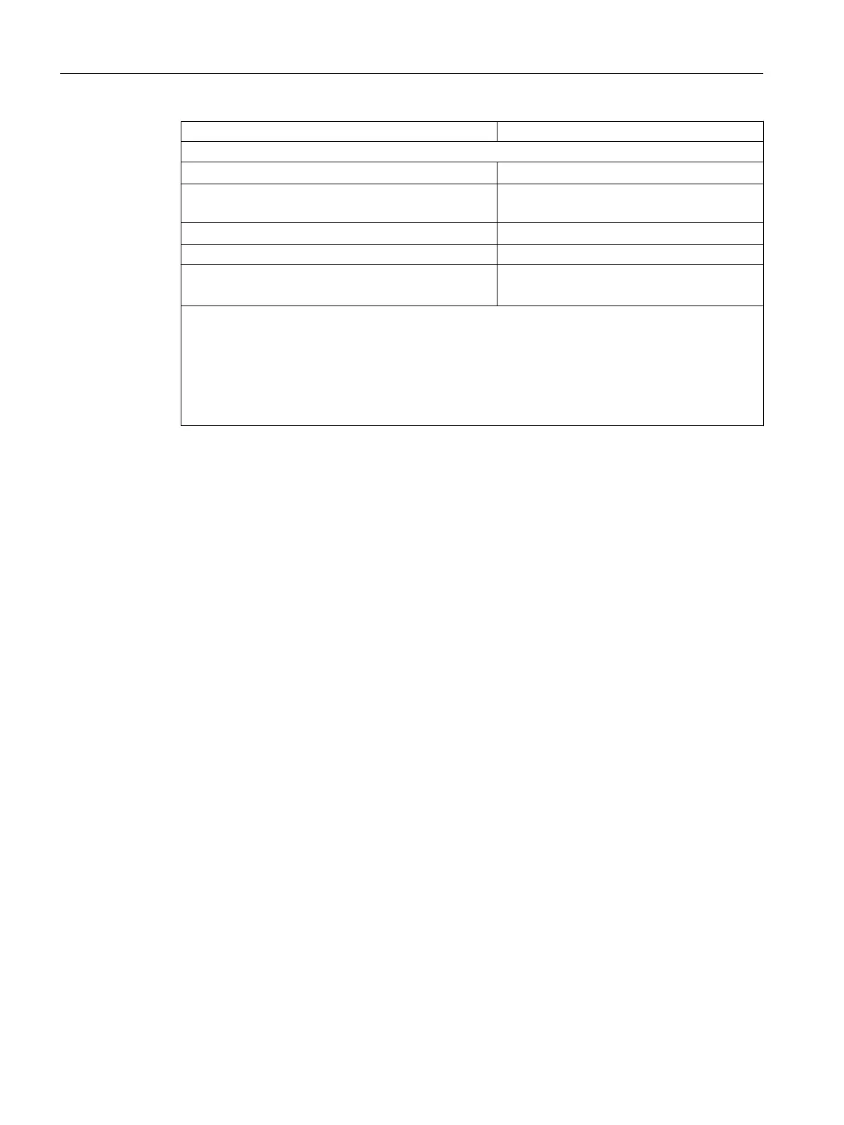
Control of a digital input Possible
Switching frequency max.
● With resistive load
100 Hz
● With an inductive load in accordance with IEC
947-51, DC 13
0.2 Hz at 1 A
0.1 Hz at 2 A
● With lamp load
Maximum 10 Hz
(Internal) limitation of inductive switch-off voltage to Maximum -30 V
Short-circuit protection for output
● Response threshold
Clocked electronically
2
2.8 to 6 A
1
A supply group always consists of 2 neighboring channels, starting from channel 0. Channels 0 and
1, 2 and 3, ... 14 and 15 therefore each form a supply group.
2
Reclosing at full load is not guaranteed after a short circuit. Measures for dealing with this problem:
● Change the signal at the output or
● Interrupt the load voltage of the module
● Briefly disconnect the load from the output
4.15 Digital output module SM 422; DO 16 x DC 20-125 V/1.5 A
(6ES7422-5EH10-0AB0)
4.15.1 Features
Overview
The SM 422; DO 16 x DC 20-125 V/1.5 A has the following features:
● 16 outputs, each channel is fused; reverse polarity protection and isolated in groups of 8
● Output current 1,5 A
● Nominal load voltage 20 to 125 VDC
● Group error display for internal faults (INTF) and external faults (EXTF)
● Programmable diagnostics
● Programmable diagnostic interrupt
● Programmable substitution value output
Digital modules
4.15 Digital output module SM 422; DO 16 x DC 20-125 V/1.5 A (6ES7422-5EH10-0AB0)
S7-400 Automation System Module Data
132 Reference Manual, Ausgabe 11/2016, A5E00850736-08

 Loading...


