5.2 Module overview
Features of the analog modules
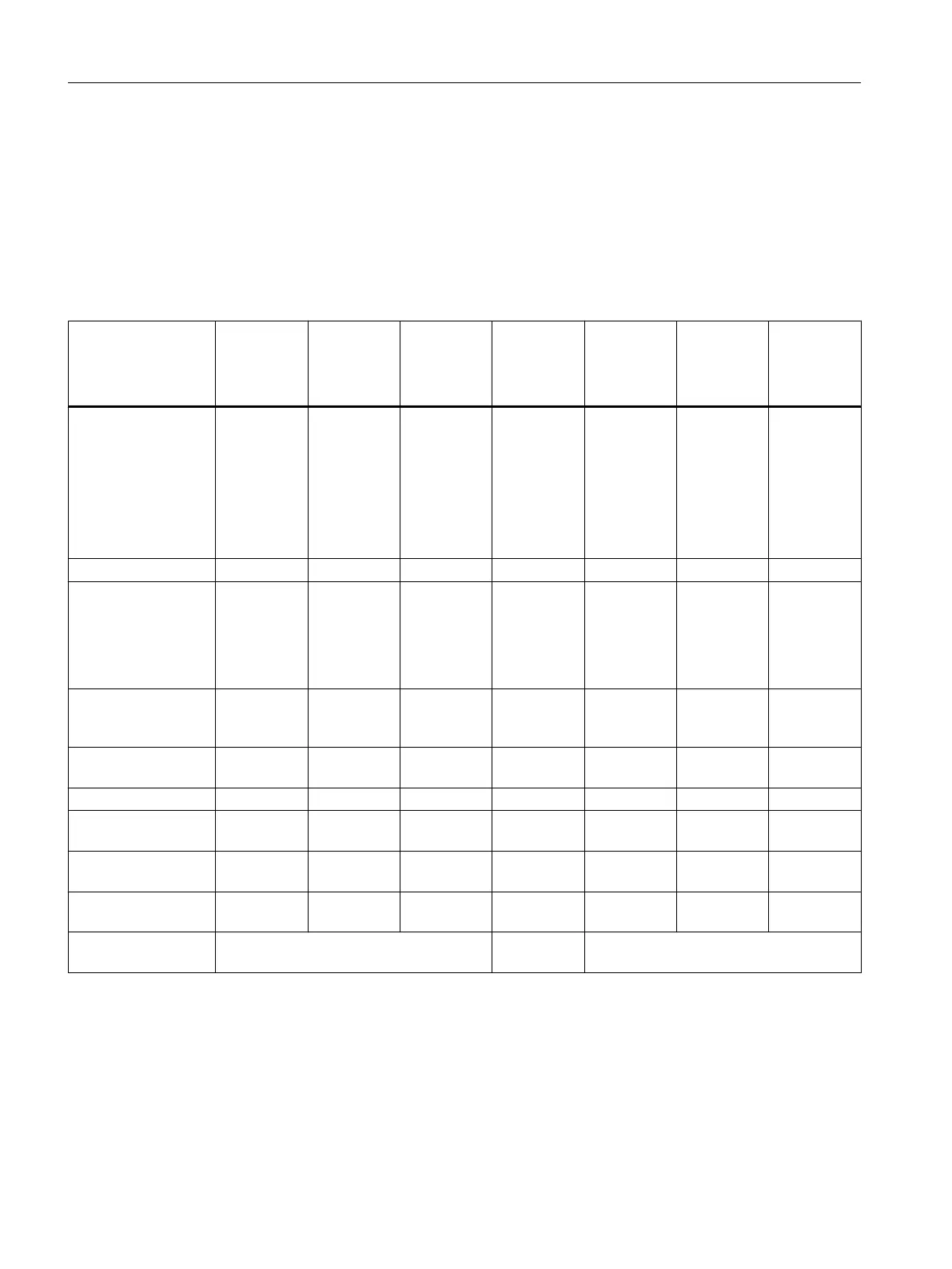
The tables below set out the main features of the analog modules. This summary is designed
to help you select the right module for your requirements.
Table 5-1 Analog input modules: Summary of features
Properties SM 431;
AI 8 x 13 bit
(-1KF00-)
SM 431;
AI 8 x 14 bit
(-1KF10-)
SM 431;
AI 8 x 14 bit
(-1KF20-)
SM 431;
AI 16 x 13 bit
(-0HH0-)
SM 431;
AI 16 x 16 bit
(-7QH00-)
SM 431;
AI 8 x RTD
16 bit
(-7KF10-)
SM 431;
AI 8 x 16 bit
(-7KF00-)
Number of inputs 8 AI for U/I
measure‐
ment
4 AI for re‐
sistance
measure‐
ment
8 AI for U/I
measure‐
ment
4 AI for re‐
sist. / temp.
measure‐
ment
8 AI for U/I
measure‐
ment
4 AI for re‐
sistance
measure‐
ment
16 inputs 16 AI for U/
I / temp.
measure‐
ment
8 AI for re‐
sistance
measure‐
ment
8 inputs 8 inputs
Resolution 13 bits 14 bits 14 bits 13 bits 16 bits 16 bits 16 bits
Type of measure‐
ment
Voltage
Current
Resistance
Voltage
Current
Resistance
Tempera‐
ture
Voltage
Current
Resistance
Voltage
Current
Voltage
Current
Resistance
Tempera‐
ture
Resistance Voltage
Current
Tempera‐
ture
Measuring principle Integrating Integrating Instantane‐
ous value
encoding
Integrating Integrating Integrating Integrating
Configurable diag‐
nostics
No No No No Yes Yes Yes
Diagnostic interrupt No No No No Can be set Yes Yes
Threshold value
monitoring
No No No No Can be set Can be set Can be set
Hardware interrupt
upon limit violation
No No No No Can be set Can be set Can be set
Hardware interrupt at
end of cycle
No No No No Can be set No No
Voltage relationships Analog section isolated from the CPU Non-isola‐
ted
Analog section isolated from the CPU
Analog modules
5.2 Module overview
S7-400 Automation System Module Data
164 Reference Manual, Ausgabe 11/2016, A5E00850736-08

 Loading...


