Points to note about checking for "Underflow" with some measuring methods and measuring ranges
There is now underflow in life-zero areas. A value that is too low or is negative is interpreted
as a wire break. You can therefore not configure the underflow check for the SM 431; AI 16 x
16 Bit for the following measuring methods and ranges:
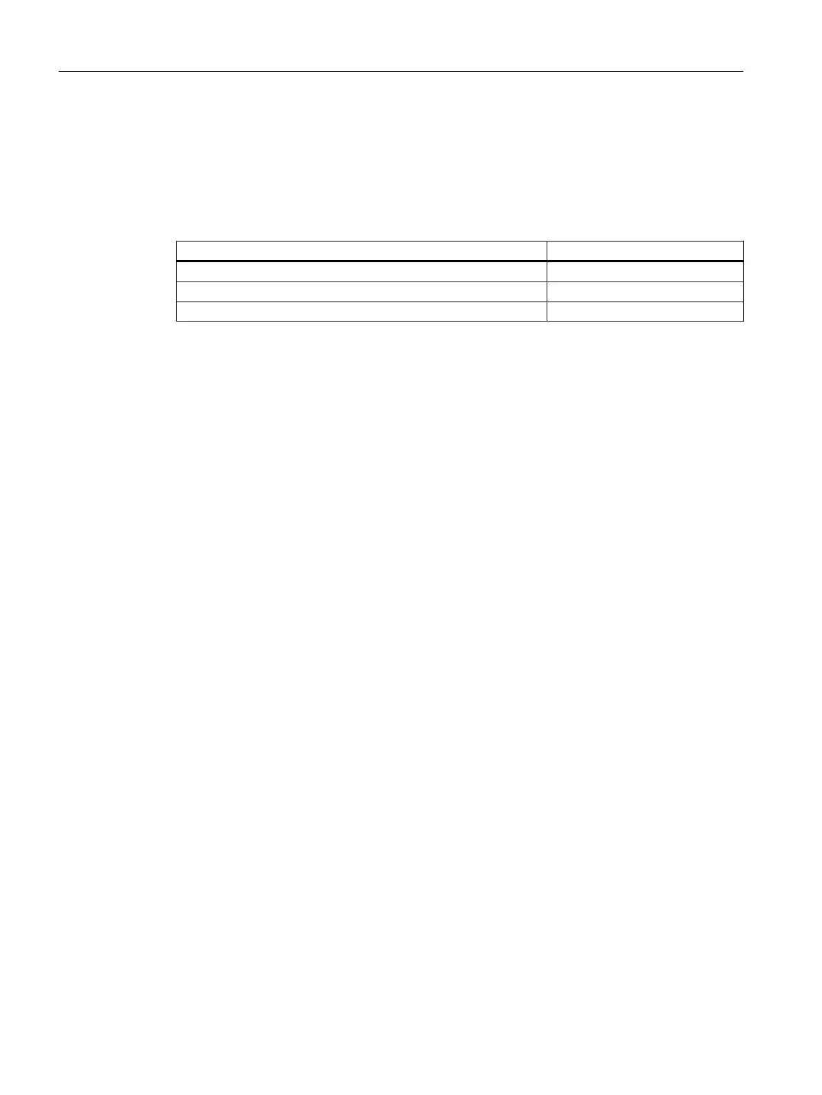
Table 5-67 Points to note when checking for "Underflow"
Measuring method Measuring range
Voltage 1 to 5 V
Current (4-wire sensor) 4 to 20 mA
Current (2-wire sensor) 4 to 20 mA
Points to note about the "Short-circuit to M" diagnostics
You can only configure the check for "Short-circuit to M" for the SM 431; AI 16 x 16 Bit for the
"Current (2-wire transducer)" measuring method.
5.24 Analog input module SM 431; AI 8 x RTD x 16 Bit
(6ES7431-7KF10-0AB0)
5.24.1 Features
Overview
The analog input module SM 431; AI 8 x RTD x 16 bit has the following features:
● 8 differential inputs for resistance thermometer
● Resistance thermometer configurable
● Linearization of characteristic curves of the resistance thermometer
● Resolution 16 bits
● Update rate 25 ms for 8 channels
● Configurable diagnostics
● Configurable diagnostic interrupt
● Configurable limit alarm
● Analog section isolated from CPU
● The maximum permitted common mode voltage between channels and central grounding
point is 120 V AC
Analog modules
5.24 Analog input module SM 431; AI 8 x RTD x 16 Bit (6ES7431-7KF10-0AB0)
S7-400 Automation System Module Data
292 Reference Manual, Ausgabe 11/2016, A5E00850736-08

 Loading...


