3.4 Operator controls and indicators
Introduction
The power supply modules of the S7-400 have essentially the same controls and indicators.
The main differences are:
● Power supply modules with a backup battery have an LED (BATTF) that indicates an empty,
defective, or missing backup battery.
● Power supply modules with two redundant backup batteries have two LEDs (BATT1F and
BATT2F) to indicate empty, defective or missing backup battery.
Operator controls and indicators
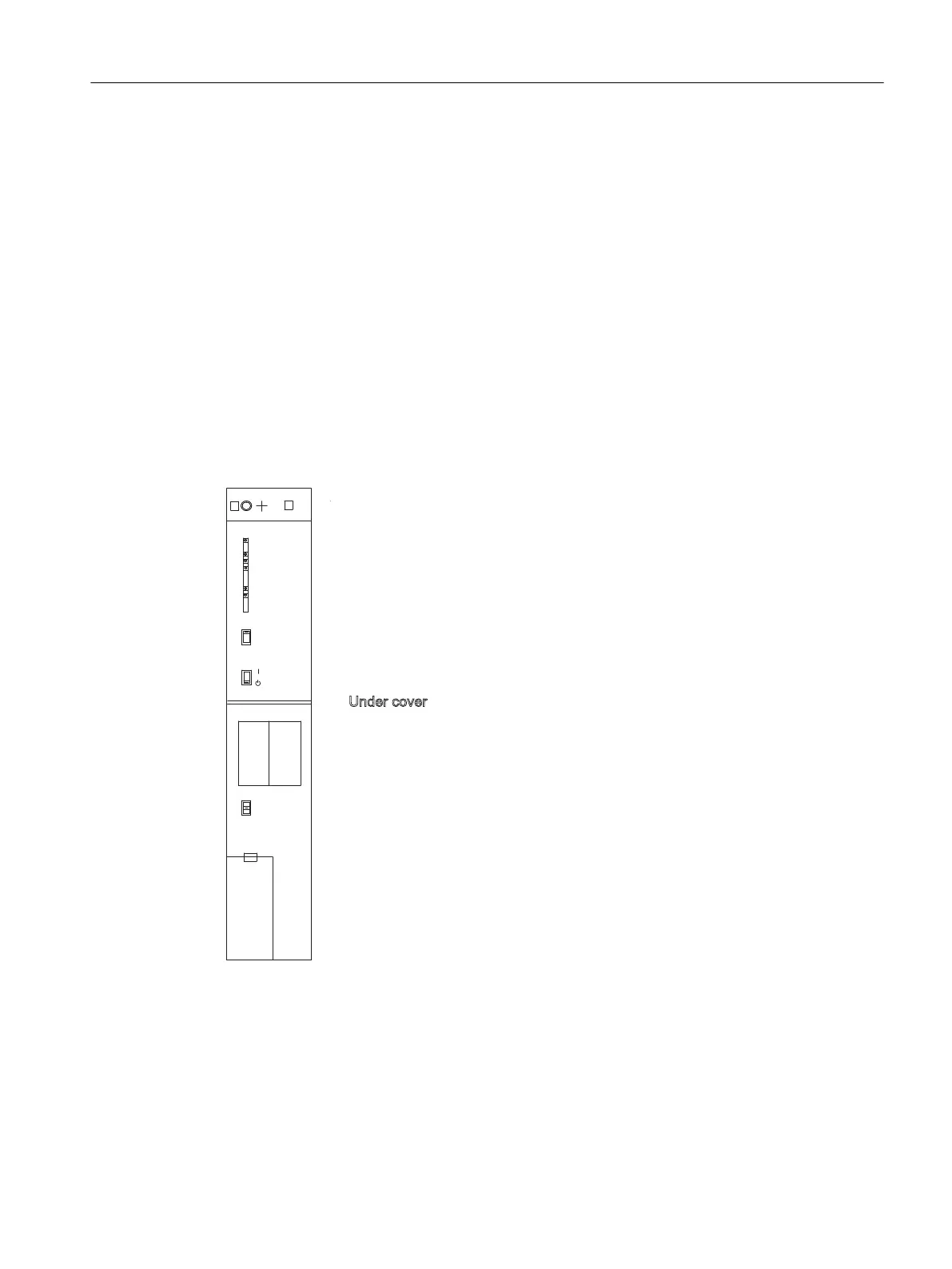
The figure shows you an example of a power supply module (PS 407 20A) with two (redundant)
backup batteries. The LEDs are at the top left of the module front plate.
36$
5$$$
;
)05
%$77,1',&
%$77
%$77
2))
,17)
%$)
%$77)
'&9
'&9
%$77)
%$77%$77
/('V,17)%$)
%$77)%$77)9
'&9'&
0RXQWLQJVFUHZ
0RXQWLQJVFUHZ
)05EXWWRQ)DLOXUH0HVVDJH5HVHW
8QGHUFRYHU
%DWWHU\FRPSDUWPHQW
6ZLWFK%$77,1',&
%$772))%$77
SLQSRZHUFRQQHFWRU
6WDQGE\VZLWFKGRHVQRWFXWRIIPDLQV
Figure 3-1 Operator controls and indicators on the PS 407 20A power supply module
Meaning of the LEDs
The meaning of the LEDs on the power supply modules is described in the tables below. The
following section contains a list of the faults indicated by these LEDs and notes on how to
acknowledge the faults.
Power supply modules
3.4 Operator controls and indicators
S7-400 Automation System Module Data
Reference Manual, Ausgabe 11/2016, A5E00850736-08 45

 Loading...


