4.17.3 Behavior of the SM 422; DO 32 x DC 24 V/0.5 A
Influence of the operating state and supply voltage on output values
The output values of the SM 422; DO 32 x DC 24 V/0.5 A depend on the operating mode of
the CPU and on the supply voltage of the module.
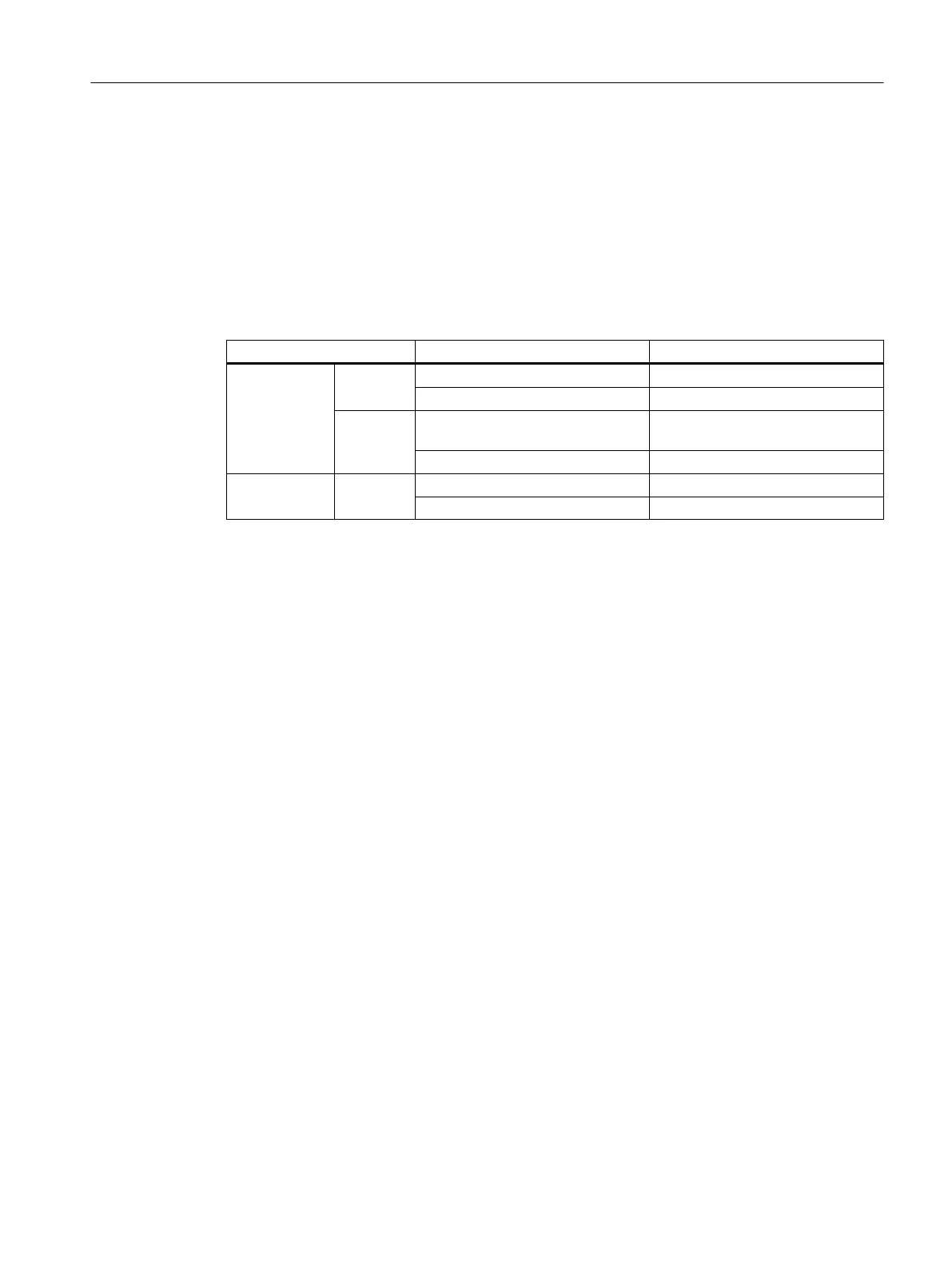
Table 4-14 Relationships of the analog output values on the CPU's operating state and on the L+
supply voltage
CPU operating mode Power supply L+ at digital module Output value of digital module
POWER ON RUN L+ present CPU value
L+ missing 0 signal
STOP L+ present Substitution value/last value (de‐
fault = 0 signal)
L+ missing 0 signal
POWER OFF - L+ present 0 signal
L+ missing 0 signal
Reaction to failure of the supply voltage
The failure of the supply voltage of the SM 422; DO 32 x DC 24 V/0.5 A is always indicated
by the EXTF LED on the module. This information is also available on the module (entry in
diagnostic data.)
Diagnostics interrupt triggering is based on parameter settings.
See also
Assigning parameters to the SM 422; DO 32 x DC 24 V/0.5 A (Page 144)
4.18 Digital output module SM 422; DO 8 x AC 120/230 V/5 A
(6ES7422-1FF00-0AA0)
Properties
SM 422; DO 8 x AC 120/230 V/5 A has the following features:
● 8 outputs, isolated in groups of 1
● Output current 5 A
● Rated load voltage 120/230 V AC
The status LEDs indicate the system state even if the front connector is not connected.
Digital modules
4.18 Digital output module SM 422; DO 8 x AC 120/230 V/5 A (6ES7422-1FF00-0AA0)
S7-400 Automation System Module Data
Reference Manual, Ausgabe 11/2016, A5E00850736-08 145

 Loading...


