4.8.2 Assigning parameters to the SM 421; DI 16 x DC 24 V
Parameter assignment
You will find a description of the general configuration of digital modules in section 5.3.
Parameters of SM 421; DI 16 x DC 24 V
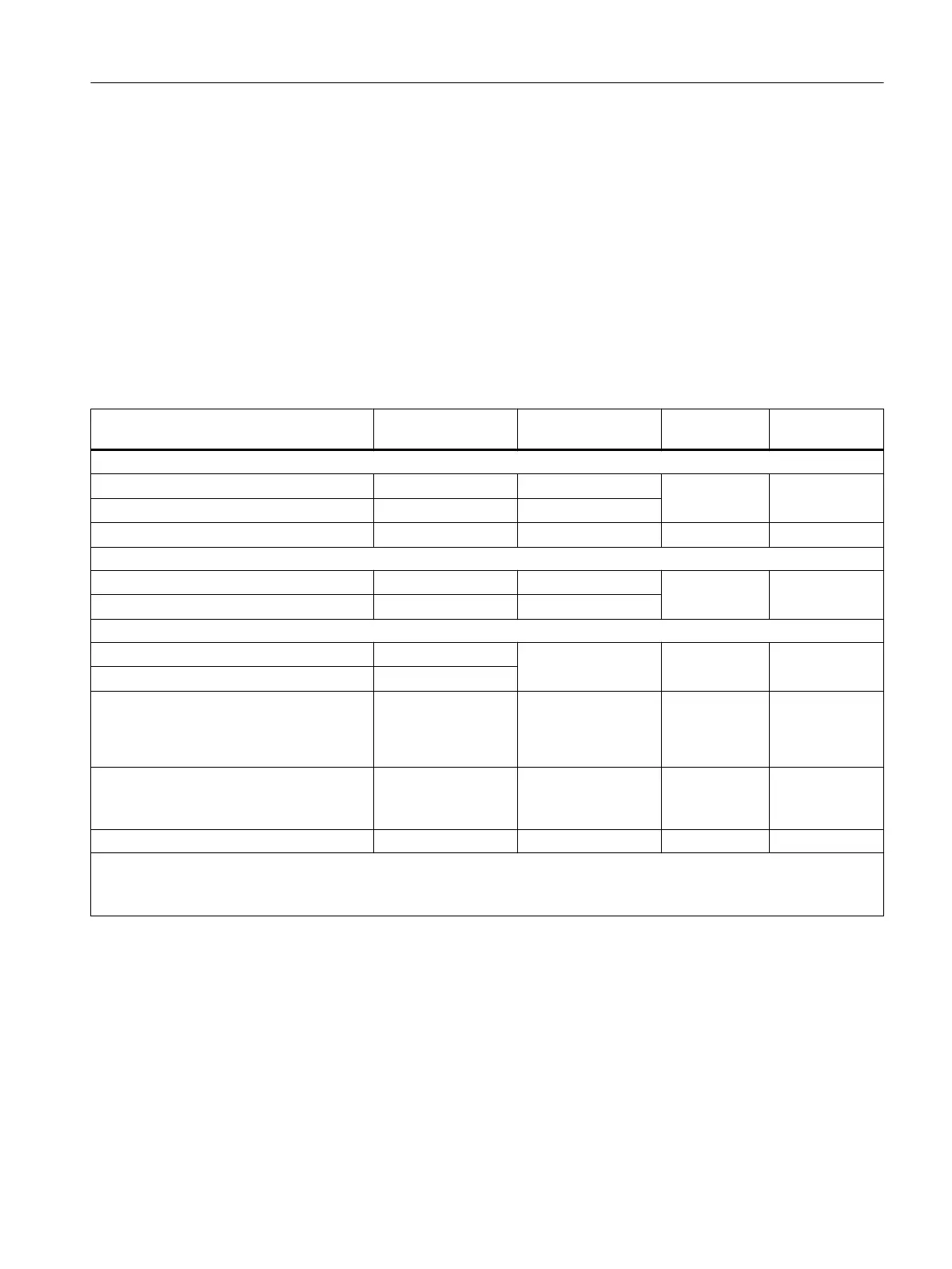
The table below shows an overview of configurable parameters and their default settings for
SM 421; DI 16 x DC 24 V.
Table 4-8 Parameters of SM 421; DI 16 x DC 24 V
Parameters Value range Default
2
Parameter
type
Scope
Enable
● Diagnostic interrupt
1
Yes/no No Dynamic Module
● Hardware interrupt
1
Yes/no No
● Destination CPU for interrupt
1 to 4 - Static Module
Diagnostics
● Wire break
Yes/no No Static Channel
Channel group
● No load voltage L+/sensor supply
Yes/no No
Hardware interrupt trigger
● Positive edge
Yes/no - Dynamic Channel
● Negative edge
Yes/no
Input delay 0.05 ms
0.1 ms
0.5 ms
3 ms
3 ms Static Channel group
Reaction to error Set substitution val‐
ue (SSV)
Hold last value (HLV)
SV Dynamic Module
Set substitution value "1" Yes/no No Dynamic Channel
1
If you use the module in ER-1/ER-2, you must set this parameter to "No" because the interrupt lines are not available in
ER-1/ER-2.
2
Only in the CR (central rack) is it possible to start up the digital modules with the default settings.
Allocating the sensor supplies to channel groups
The two sensor supplies of the module are used to supply two channel groups: Inputs 0 to 7
and inputs 8 to 15. You also configure diagnostics for the sensor supply at those two channel
groups.
Digital modules
4.8 Digital input module SM 421; DI 16 x DC 24 V (6ES7421-7BH01-0AB0)
S7-400 Automation System Module Data
Reference Manual, Ausgabe 11/2016, A5E00850736-08 105

 Loading...


