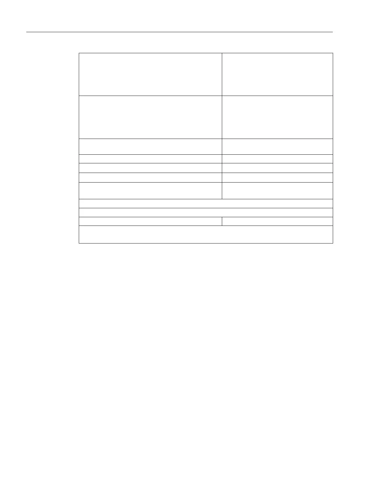
● Status recognition only
Input delay for channel groups 0.05 ms/0.05 ms
Input delay for channel groups 0.05 ms/0.1 ms or
0.1 ms/0.1 ms
Input delay for channel groups ≥ 0.5 ms
Maximum 50 µs
Maximum 70 µs
Maximum 180 µs
● Status recognition and hardware interrupt enable
Input delay for channel groups 0.05 ms/0.05 ms 2)
Input delay for channel groups 0.05 ms/0.1 ms or
0.1 ms/0.1 ms
Input delay for channel groups ≥ 0.5 ms
Maximum 60 µs
Maximum 80 µs
Maximum 190 µs
Internal processing time for diagnostics/diagnostic inter‐
rupt
Maximum 5 ms
Input delay
● Configurable
Yes
● Rated value
0.05 / 0.1 /0.5 / 3 ms
● Input frequency
(with 0.1 ms delay time)
< 2kHz
Values included in cycle and response times.
Sensor circuit
Sensor resistor circuit for wire-break monitoring 10 to 18 kΩ
1
The filter times for the selected input delay are added to the total runtime.
2
Substitute value function; diagnostics and diagnostic interrupt must not be selected.
Digital modules
4.8 Digital input module SM 421; DI 16 x DC 24 V (6ES7421-7BH01-0AB0)
S7-400 Automation System Module Data
104 Reference Manual, Ausgabe 11/2016, A5E00850736-08

 Loading...


