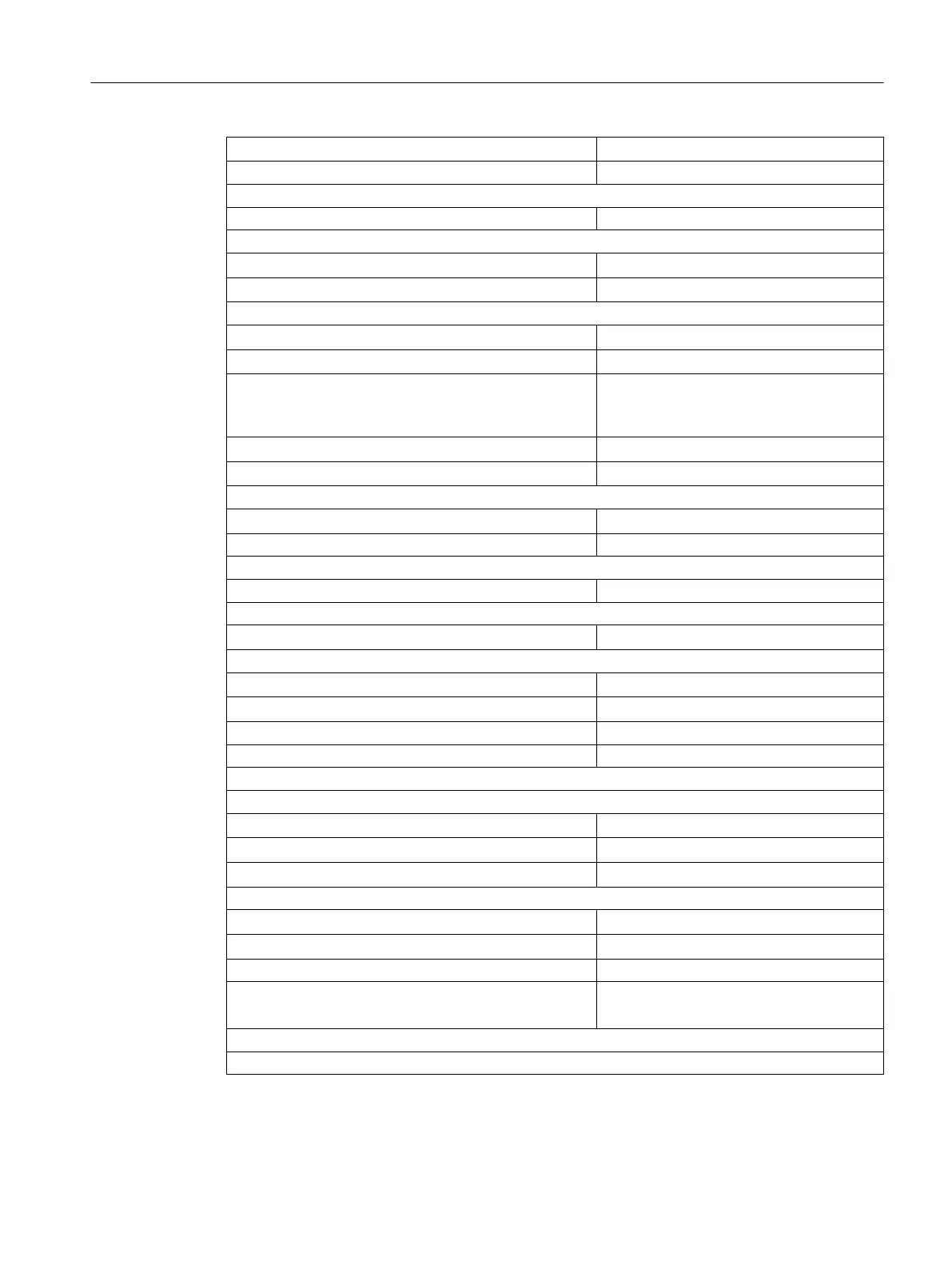
● from supply voltage L+
120 mA maximum
Module power loss Typ. 5 W
Status, interrupts, diagnostics
Status display Green LED per channel
Interrupts
● Hardware interrupt
Configurable
● Diagnostic interrupt
Configurable
Diagnostic functions
● Supply voltage monitoring for electronics
Yes
● Load voltage monitoring
Green LED per group
● Group fault display
for internal fault
for external fault
red LED (INTF)
red LED (EXTF)
● Channel fault display
None
● Diagnostic information can be read out
Yes
Monitoring for
● Wire break
I < 1 mA
Substitute values can be connected Yes
Sensor supply outputs
Number of outputs 2
Output voltage
● loaded
At least L+(-2.5 V)
Output current
● Rated value
120 mA
● Permitted range
0 to 150 mA
Additional (redundant) supply Possible
Short-circuit protection Yes, electronic
Data for selecting a sensor
Input voltage
● Rated value
24 V DC
● For "1" signal
11 to 30 V
● For "0" signal
-30 to 5 V
Input current
● For "1" signal
6 to 12 mA
● For "0" signal
< 6 mA
Input characteristic In accordance with IEC 61131; type 2
Connection of 2-wire BEROs
● Permissible quiescent current
Possible
3 mA maximum
Time, frequency
Internal preparation time
1
for
Digital modules
4.8 Digital input module SM 421; DI 16 x DC 24 V (6ES7421-7BH01-0AB0)
S7-400 Automation System Module Data
Reference Manual, Ausgabe 11/2016, A5E00850736-08 103

 Loading...


