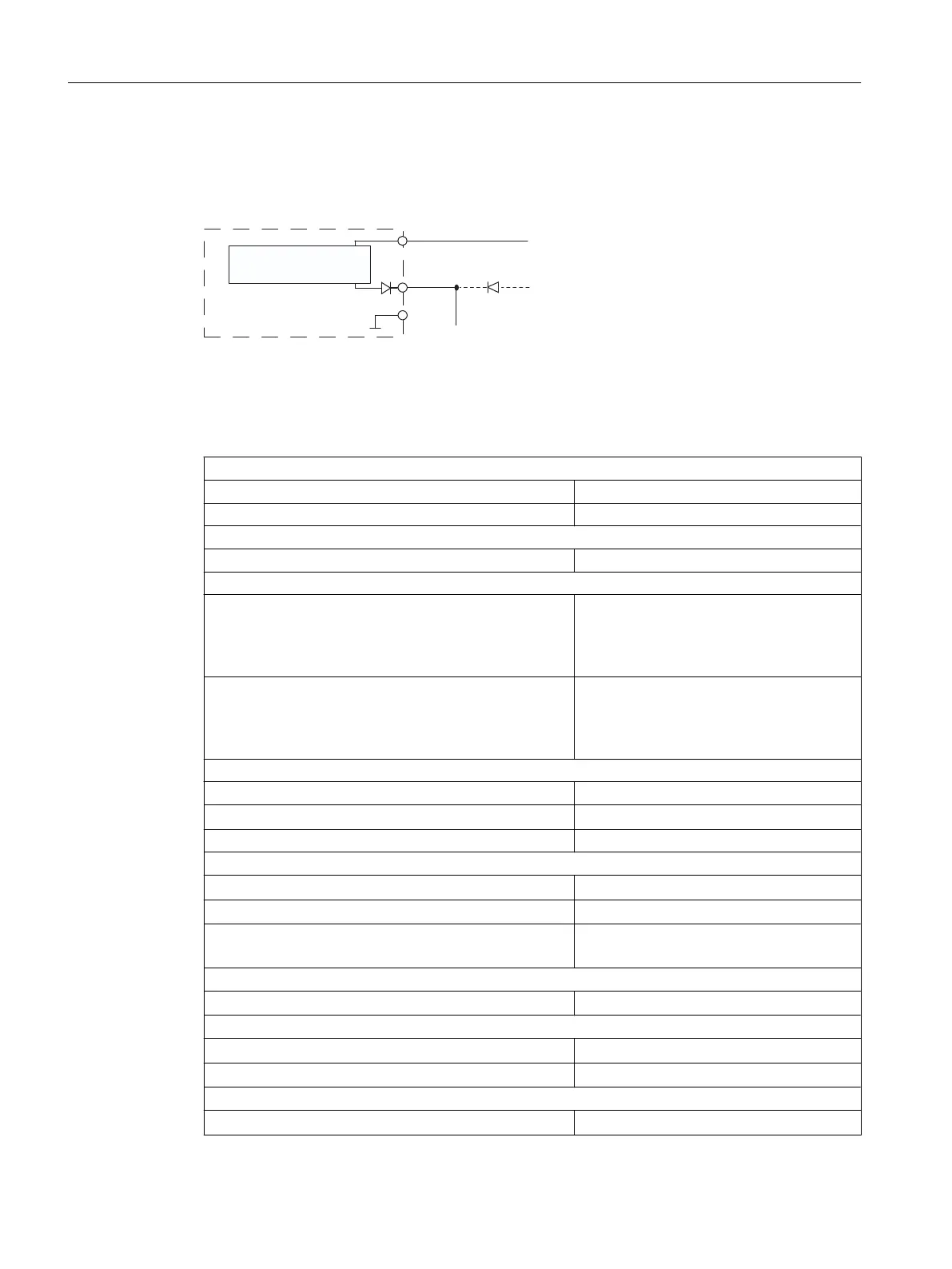
Connection diagram for redundant sensor supply
The image below shows how sensors can be supplied with a redundant voltage source over
Vs (e.g. through another module).
Vs
M
L+
1 L+
2 L+
±
Short-circuit-
proof driver
Digital input
module
to the sensors
Figure 4-4 Connection diagram for redundant sensor supply for SM 421; DI 16 x 24 V DC
Technical specifications for SM 421; DI 16 x 24 V DC
Dimensions and weight
Dimensions W x H x D (mm) 25 x 290 x 210
Weight ca. 600 g
Module-specific data
Number of inputs 16
Cable length
● Unshielded, input delay
0.1 ms
0.5 ms
3 ms
20 m maximum
50 m maximum
600 m maximum
● Shielded, input delay
0.1 ms
0.5 ms
3 ms
30 m maximum
70 m maximum
1000 m maximum
Voltage, current and potential
Rated supply voltage of electronics and sensor L+ 24 V DC
● Reverse polarity protection
Yes
Number of inputs that can be enabled simultaneously 16
Electrical isolation
● Between channels and backplane bus
Yes
● Between channels and electronics power supply
No
● Between channels
in groups of
Yes
8
Permissible potential difference
● Between different circuits
60 V DC/30 V AC (SELV)
Insulation tested at
● channels against rear panel and load voltage L+
500 V DC
● Between channel groups
500 V DC
Current consumption
● from backplane bus (5 V)
130 mA maximum
Digital modules
4.8 Digital input module SM 421; DI 16 x DC 24 V (6ES7421-7BH01-0AB0)
S7-400 Automation System Module Data
102 Reference Manual, Ausgabe 11/2016, A5E00850736-08

 Loading...


