9.2 Fan monitoring in the fan subassemblies
LEDs
The three red LEDs of the fan subassembly are assigned to the individual fans. From left to
right, these are:
F1 - for fan 1
F2 - for fan 2
F3 - for fan 3
Fans
The fans have a redundant design. The fan subassembly continues to function even if one fan
fails.
Fan monitoring
The function of the fans is controlled by means of speed monitoring. If the speed of a fan drops
below the limit speed of 1750 rpm, the LED assigned to it lights up. In addition, the relay K1
drops out.
If the speed of a second fan drops below the limit speed, the LED assigned to it lights up; in
addition, the relay K2 drops out.
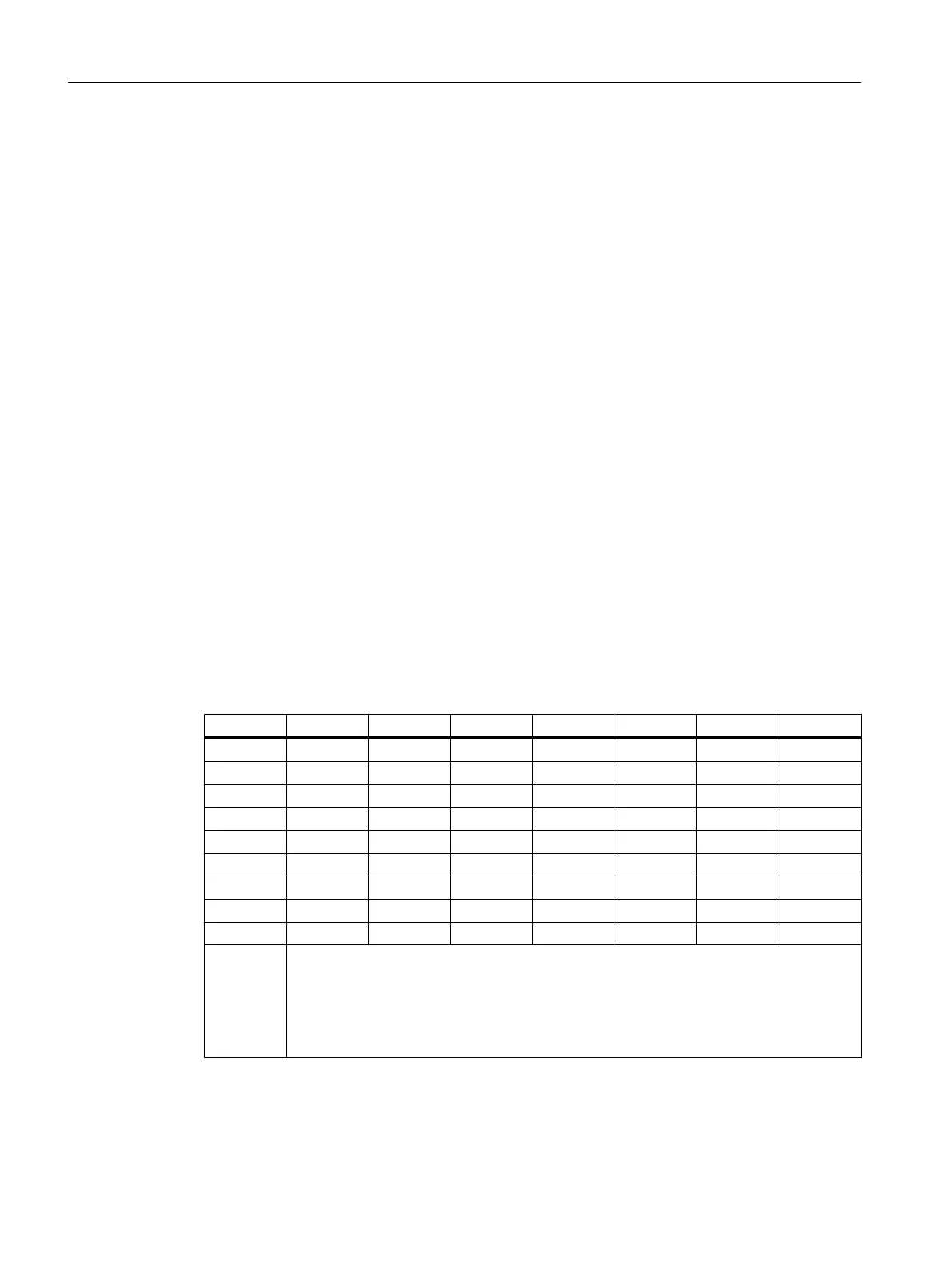
The following table is the function table for the fan monitoring.
Table 9-1 Function of fan monitoring
Fan1 Fan2 Fan3 LED F1 LED F2 LED F3 Relay K1 Relay K2
- - - H H H - -
- - + H H D - -
- + - H D H - -
+ - - D H H - -
- + + H D D - +
+ - + D H D - +
+ + - D D H - +
+ + + D D D + +
-* -* -* D* D* D* -* -*
+
-
D
H
*
Fan in operation or relay picked up
Fan failed or relay dropped out
LED is dark
LED lights up
At power off
Example of a message concept
You can check the fault-free functioning of the fan subassembly using digital inputs.
Cable duct and fan subassemblies
9.2 Fan monitoring in the fan subassemblies
S7-400 Automation System Module Data
378 Reference Manual, Ausgabe 11/2016, A5E00850736-08

 Loading...


