5.8.2 Parameters of analog input modules
Overview
Analog input modules use a subset of the parameters and value range listed in the table below,
based on their functionality. For information on subsets "supported" by specific analog
modules, refer to the section dealing with the relevant module.
The defaults apply if you have not set any parameters in
STEP 7
.
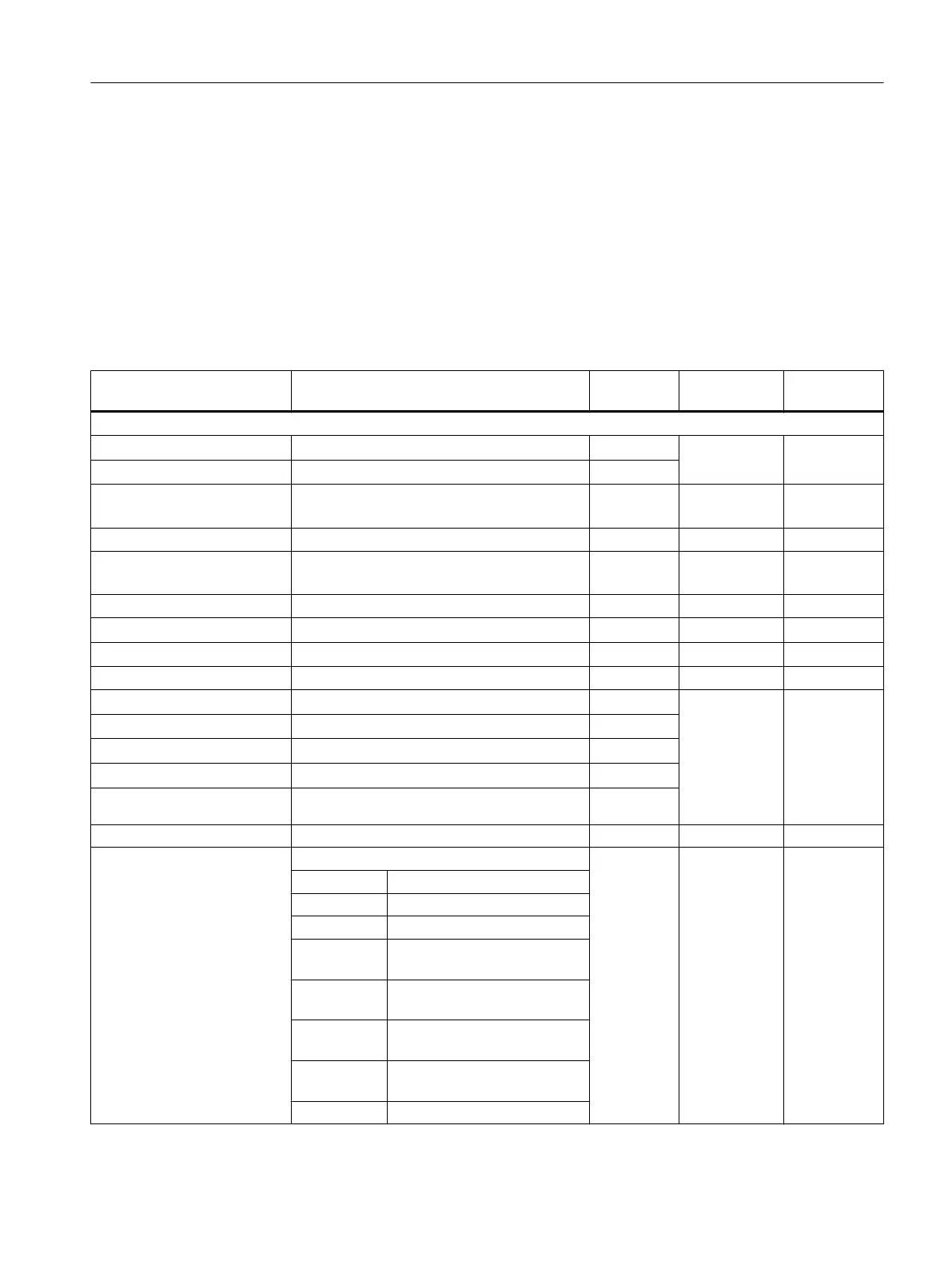
Table 5-41 Parameters of analog input modules
Parameters Value range Default
2
Parameter
type
Scope
Enable
● Diagnostic interrupt
1
Yes/no No Dynamic Module
● Hardware interrupt
1
Yes/no No
● Destination CPU for
interrupt
1 to 4 - Static Module
Hardware interrupt trigger
● End of scan cycle reached
at input
Yes/no No Static Channel
May be restricted by the measuring range
● High limit
32511 to - 32512 - Dynamic Channel
● Low limit
-32512 to 32511
Diagnostics
● Wire break
Yes/no No
Static
Channel
● Reference channel error
Yes/no No
● Underflow
Yes/no No
● Overflow
Yes/no No
● Short-circuit to M
Yes/no No
Measurement
● Measuring method
Disabled U
Static
Channel
U Voltage
4DMU Current (4-wire sensor)
2DMU Current (2-wire sensor)
R-4L Resistance (4-conductor con‐
nection)
R-3L Resistance (3-conductor con‐
nection)
RTD-4L Thermal resistance (linear, 4-
conductor connection)
RTD-3L Thermal resistance (linear, 3-
conductor connection)
TC-L Thermocouple (linear)
Analog modules
5.8 Assigning parameters to analog modules
S7-400 Automation System Module Data
Reference Manual, Ausgabe 11/2016, A5E00850736-08 201

 Loading...


