5.19.3 Measuring methods and measuring ranges of SM 431; AI 8 x 13 Bit
Measuring methods
You can set the measuring method at the input channels:
● Voltage measurement
● Current measurement
● Resistance measurement
You perform the setting with the "measuring method" parameter in STEP 7.
Circuit for resistance measurement
The following conditions apply when measuring the resistance with the SM 431; AI 8 x 13 Bit:
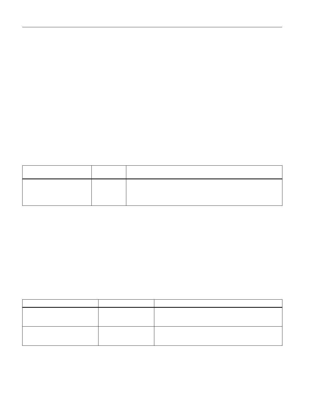
Table 5-46 Channels for resistance measurement of the SM 431; AI 8 x 13 Bit
Measuring type parameter Permissible
for channel n
Condition
Resistance
(4-conductor connection)
0, 2, 4 or 6 You must disable the "Measuring type" parameter for channels n+1 (1, 3,
5, 7).
Reason: The connections of channel n+1 are used to supply the resistance
that is connected to channel n.
Unused channels
Unused channels can be left open. You can improve the noise immunity of the module in a
measuring environment with serious interference by short-circuiting the channels and
connecting to M
ANA
. For unused channels, set the "measuring method" parameter to
"deactivated". This reduces the module's cycle time.
Measuring ranges
Set the measuring ranges at the "measuring range" parameter in
STEP 7
.
Table 5-47 Measuring ranges of the SM 431; AI 8 x 13 Bit
Selected measuring method Measuring range Description
V: Voltage ±1 V
1 V to 5 V
±10 V
The digitized analog values are listed in the section "Repre‐
sentation of analog values for output channels" in the voltage
measuring range.
2DMU: Current
(2-wire transducer)
4 to 20 mA The digitized analog values are listed in the section "Repre‐
sentation of analog values for output channels in the current
measuring range".
Analog modules
5.19 Analog input module SM 431; AI 8 x 13 Bit (6ES7431-1KF00-0AB0)
S7-400 Automation System Module Data
236 Reference Manual, Ausgabe 11/2016, A5E00850736-08

 Loading...


