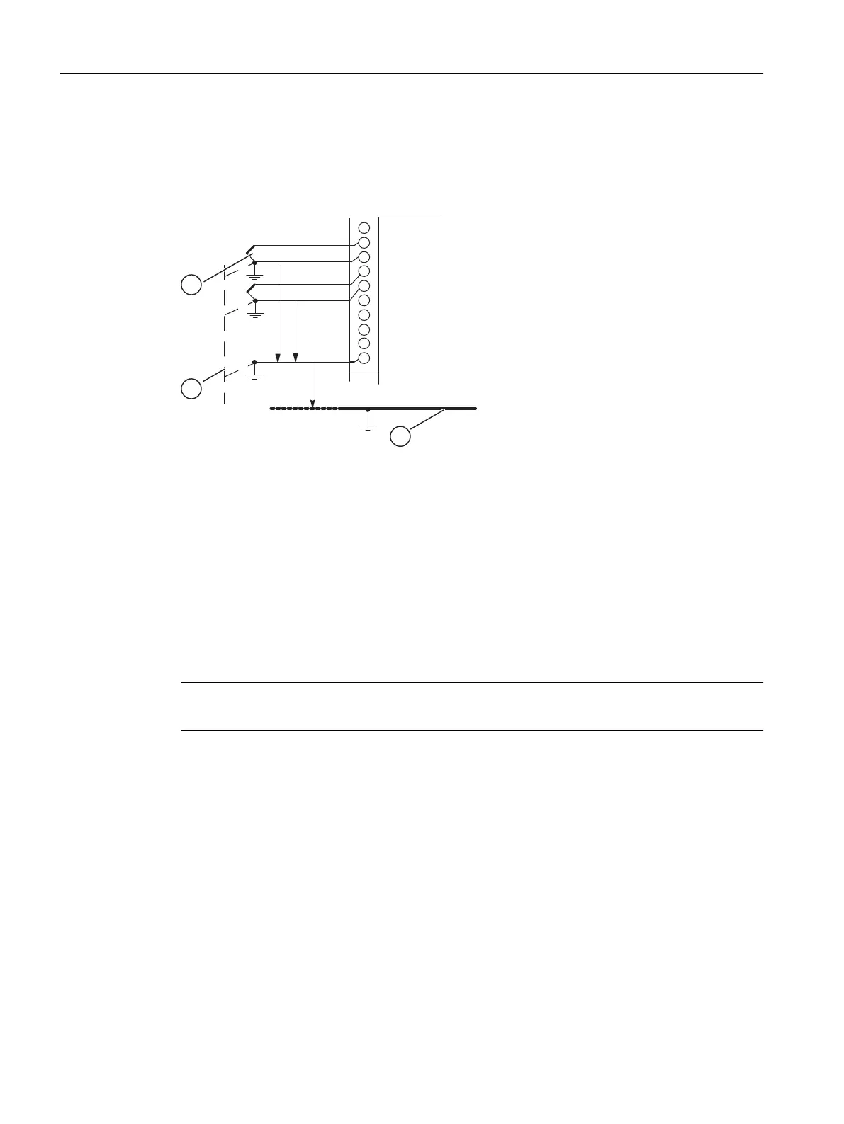
Connecting non-isolated sensors
Depending on local conditions or interference, potential differences U
CM
(static or dynamic)
can occur between the locally distributed measuring points. If the permitted value for U
CM
is
exceeded, there must be equipotential bonding conductors between the measuring points.
Figure 5-6 Connecting non-isolated sensors to an isolated AI
(1) Non-isolated sensors
(2) Chassis ground
(3) Equipotential bonding conductor
M +: Measuring line (positive)
M -: Measuring line (negative)
M
ANA
: Reference potential of the analog measuring circuit
U
ISO
: Potential difference between M
ANA
and chassis ground
Note
Do not use non-isolated 2-wire transducers and non-isolated resistance-type sensors!
Analog modules
5.9 Connecting sensors to analog inputs
S7-400 Automation System Module Data
206 Reference Manual, Ausgabe 11/2016, A5E00850736-08

 Loading...


