To ensure that the permissible value for U
CM
is not exceeded during use in heavily EMC-
affected environments, connect M- to MANA in modules with an M
ANA
connection.
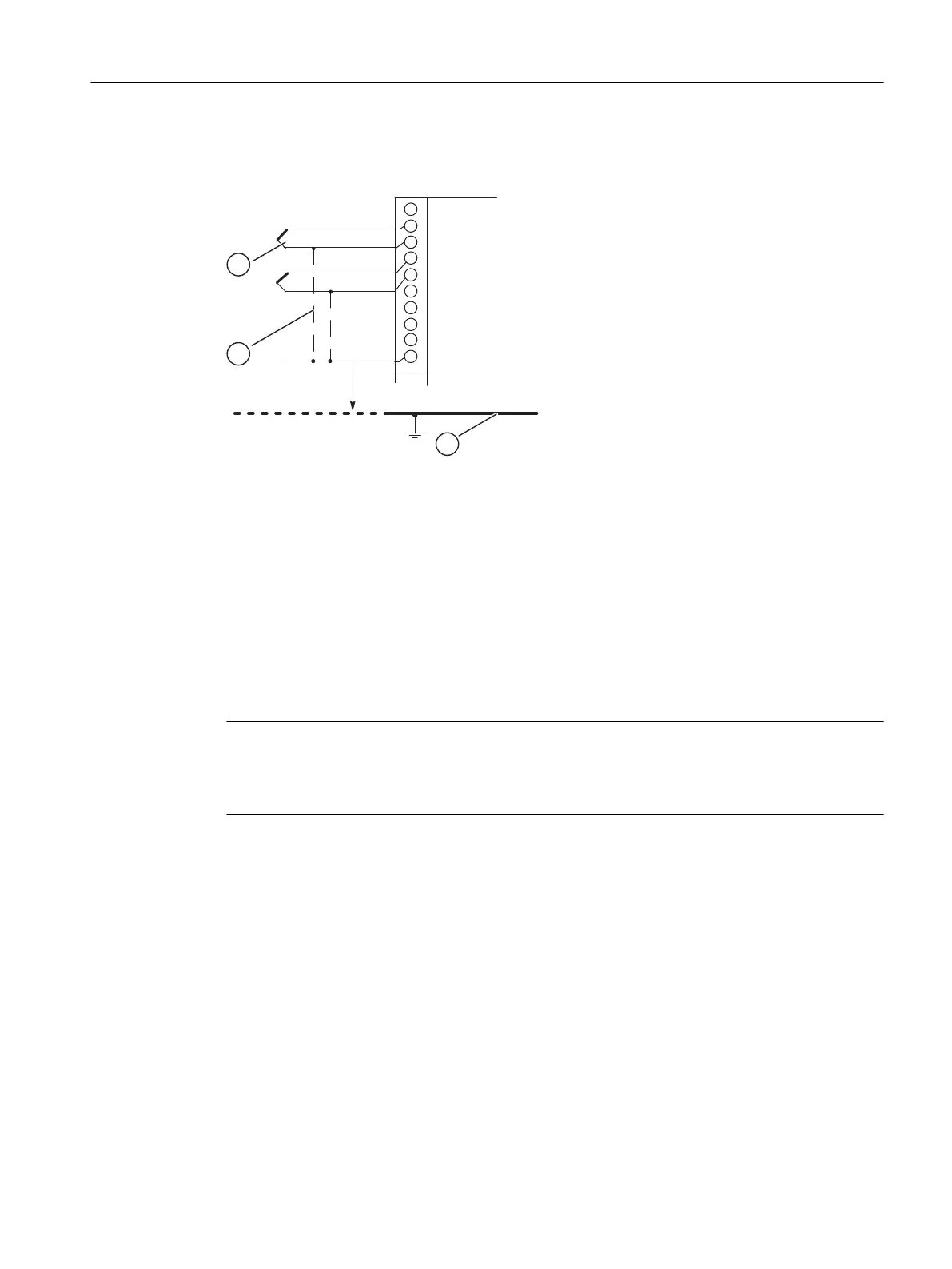
Figure 5-5 Connecting isolated sensors to an electrically isolated AI
(1) Electrically isolated sensors
(2) Chassis ground
(3) Connection required for modules with M
ANA
M +: Measuring line (positive)
M -: Measuring line (negative)
M
ANA
: Reference potential of the analog measuring circuit
U
ISO
: Potential difference between M
ANA
and chassis ground
Note
Do not connect M- to MANA when connecting 2-wire transducers for current measurement
and when connecting resistance-type sensors. This also applies to inputs which are
programmed accordingly, but remain unused.
Non-isolated sensors
The isolated sensors are not connected with the local ground potential (chassis ground). When
using non-isolated sensors, you must connect M
ANA
to chassis ground.
Analog modules
5.9 Connecting sensors to analog inputs
S7-400 Automation System Module Data
Reference Manual, Ausgabe 11/2016, A5E00850736-08 205

 Loading...


