Setting the input delay for channel groups
You can only set the input delay for each group of channels. In other words, the setting for
channel 0 applies to inputs 0 to 7 and the setting for channel 8 applies to inputs 8 to 15.
Note
The parameters that are entered for the remaining channels (1 to 7 and 9 to 15) must be equal
to the value 0 or 8, otherwise those channels will be reported as being incorrectly configured.
Any hardware interrupts that have occurred in the meantime will be reported after
acknowledgement.
Optimum signal propagation delays
You can achieve the fastest signal propagation delay with the following settings:
● Both channel groups are configured with an input delay of 0.5 ms
● The diagnostics parameter is disabled
● The diagnostic interrupt parameter is disabled
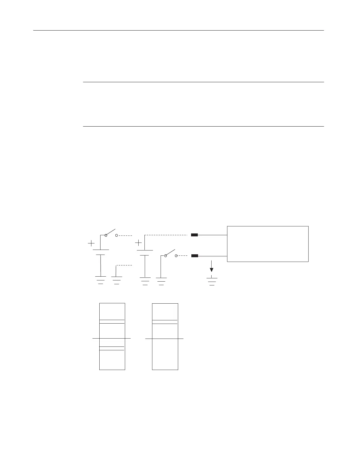
Circuit as for active high or active low input
"1"
"0"
0V
- L+
U_s
"1"
U_s
DI_x
"1"
"0"
0V
L+
- L+
U_s
DI_xN
SM 421 DI 16xUC 24/60 V
L+
U_s
Channel x of the
Active high
Source input
Input threshold
Figure 4-7 Circuit as for active high or active low input
Digital modules
4.10 Digital input module SM 421; DI 16 x UC 24/60 V (6ES7421-7DH00-0AB0)
S7-400 Automation System Module Data
Reference Manual, Ausgabe 11/2016, A5E00850736-08 117

 Loading...


