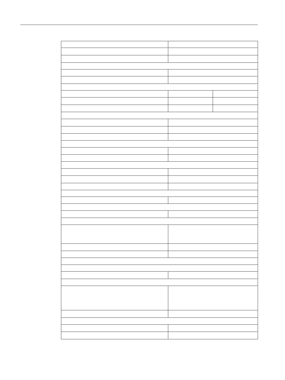
Cable length
● Unshielded
Max. 600 m
● Shielded
Max. 1000 m
Voltages, currents, electrical potentials
Nominal load voltage L1 20 to 138 V DC
● Reverse polarity protection
Yes, with fuse
Total current of the outputs
1)
With fan subassembly
● Up to 40° C
Max. 16 A 21 A
● Up to 60° C
Max. 8 A 14 A
Electrical isolation
● Between channels and the backplane bus
Yes
● Between channels
Yes
In groups of 8
Permissible potential difference
● Between outputs of different groups
250 VAC
Isolation test voltage 1500 VAC
Current consumption
● From the backplane bus (5 V)
Max. 700 mA
● From load voltage L+ (no load)
Max. 2 mA
Power loss of the module Typ. 10 W
Status, interrupts, diagnostics
Status display Green LED per channel
Interrupts
● Diagnostic interrupt
Programmable
Diagnostic functions
● Group error display
for internal disruption
for external disruption
Configurable
Red LED (INTF)
Red LED (EXTF)
● Diagnostic information dump
Yes
Injection of substitution values Yes, programmable
Actuator selection data
Output voltage
● With "1" signal
Min. L+ (-1.0 V)
Output current
● With signal "1"
Rated value
Permissible range
Permissible peak current
1.5 A
10 mA to 1.5 A
Maximum 3 A (for 10 ms)
● With "0" signal (residual current)
Max. 0,5 mA
Output delay (resistive load)
● At "0" to "1" transitions
Max. 2 ms
● With "1" to "0"
Max. 13 ms
Digital modules
4.15 Digital output module SM 422; DO 16 x DC 20-125 V/1.5 A (6ES7422-5EH10-0AB0)
S7-400 Automation System Module Data
134 Reference Manual, Ausgabe 11/2016, A5E00850736-08

 Loading...


