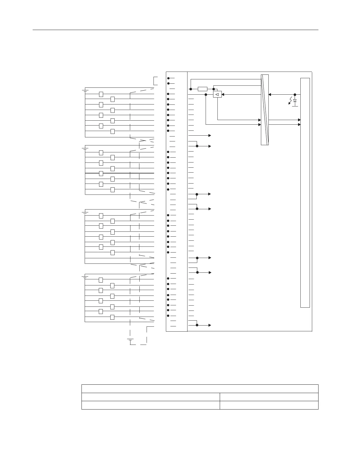
Connection and circuit diagram for SM 422; DO 32 x DC 24 V/0.5 A
L+
3L+
2L+
4L+
1L+
24 V
1
2
3
4
5
6
7
8
9
11
12
13
14
15
16
17
18
19
20
21
22
23
24
25
26
27
28
29
30
31
32
33
34
35
36
37
38
39
40
41
42
43
44
45
46
47
48
1
2
4
7
0
3
5
6
1
2
4
7
0
3
5
6
1
2
4
7
0
3
5
6
1
2
4
7
0
3
5
6
4M
1L+
2L+
2L+
3L+
3L+
4L+
4L+
INTF
EXTF
1M
10
1M
2M
2M
3M
3M
4M
4M
4L+
3M
3L+
2M
1M
2L+
Process
Module
%DFNSODQHEXVFRQQHFWLRQ
1L+ monitoring
Control
Monitoring of internal voltage
Control
Diagnostics
Output status
Channel status
display
Front connector jumper
Figure 4-14 Connection and circuit diagram for SM 422; DO 32 x DC 24 V/0.5 A
Technical specifications for SM 422; DO 32 x DC 24 V/0.5 A
Dimensions and weight
Dimensions W x H x D (mm) 25 x 290 x 210
Weight ca. 600 g
Digital modules
4.17 Digital output module SM 422; DO 32 x DC 24 V/0.5 A (6ES7422-7BL00-0AB0)
S7-400 Automation System Module Data
Reference Manual, Ausgabe 11/2016, A5E00850736-08 141

 Loading...


