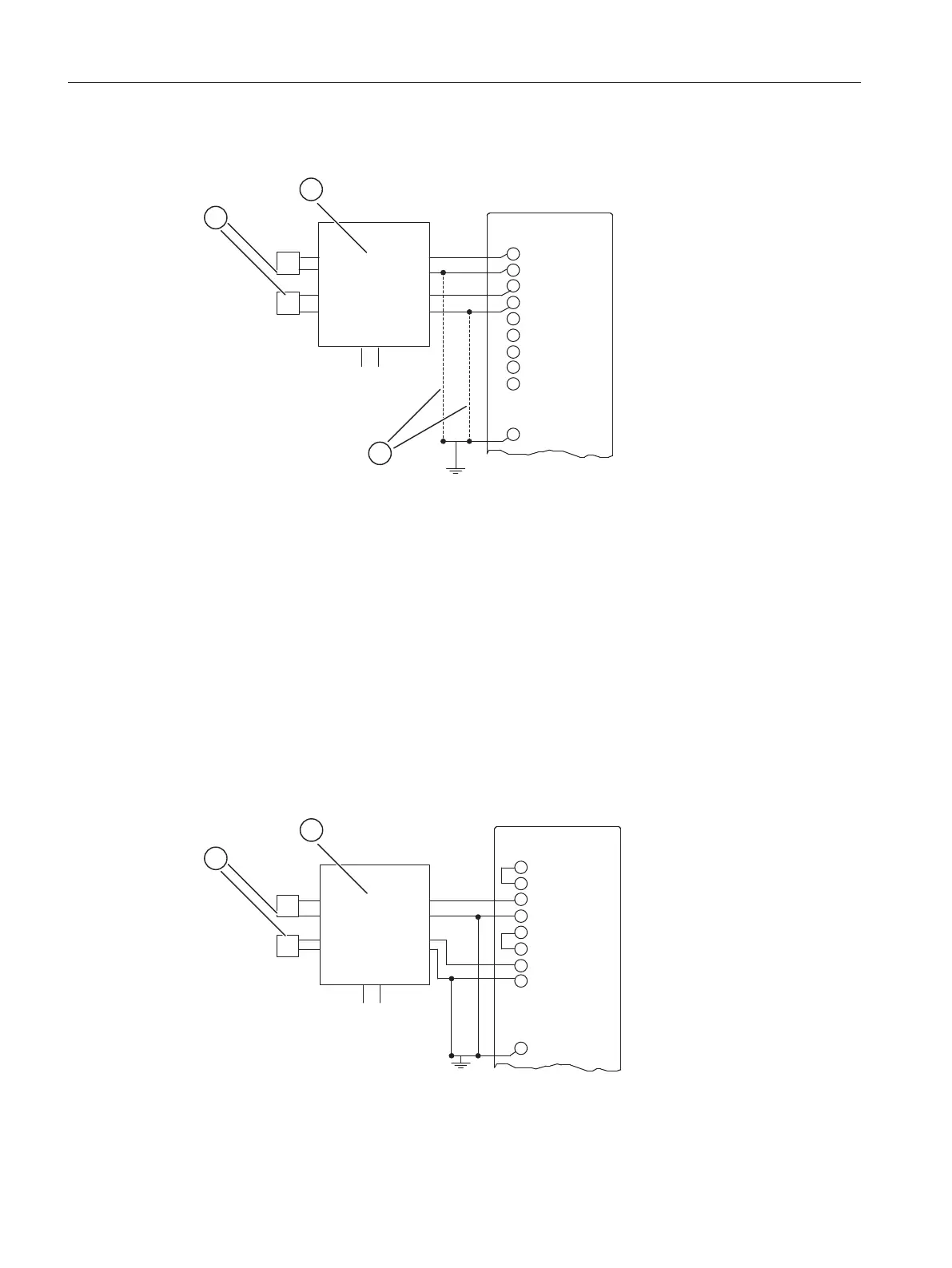
Connecting 4-wire transducers
Figure 5-10 Connecting 4-wire transducers to an AI
M +: Measuring line (positive)
M -: Measuring line (negative)
M
ANA
: Reference potential of the analog measuring circuit
U
H
: Auxiliary voltage
(1) Sensor, for example, pressure gauge
(2) 4-wire transducer
(3) Connection required for modules with M
ana
SM 431; 8 x 13 Bit: Connecting 4-wire transducers
To ensure that the permissible value for U
CM
is not exceeded, you must connect the M-cables
to M
ANA
.
1
2
M
+
-
+
-
U
H
M
I+
M
I+
M-
M
V+
M
V+
M
I+
M
I+
M-
P
P
Figure 5-11 Connecting 4-wire transducers to an SM 431; 8 x 13 Bit
Analog modules
5.11 Connecting current sensors
S7-400 Automation System Module Data
210 Reference Manual, Ausgabe 11/2016, A5E00850736-08

 Loading...


