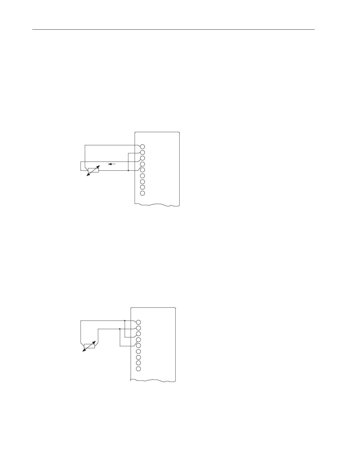
3-conductor connection of a resistance thermometer
With a 3-conductor connection to modules with 4 terminals per resistance thermometer, you
must set up a jumper between M-
and I
C
- and SE- and AGND
(see Figure).
The module compensates in this circuit for the effect of the line resistance between the module
and the resistance thermometer/resistor.
Make sure that the connected cables I
C
+ and M+ and SO and SE+ are directly connected to
the resistance thermometer.
To get an accurate measurement, make sure that the connected cables M+, I
C
+ and I
C
- and
SE+, SO and AGND are the same length and have the same cross-section.
Figure 5-13 3-conductor connection of a resistance thermometer to an electrically isolated analog input
I
C+
Constant current line (positive)
I
C-
Constant current line (negative)
M
+
Measuring line (positive)
M
-
Measuring line (negative)
2-conductor connection of a resistance thermometer
For 2-conductor connections, bridge the M
+
and I
C+
, and the M
-
and I
C-
terminals of the module.
Note: Cable resistance is also measured.
Figure 5-14 2-conductor connection of a resistance thermometer to an electrically isolated analog input
Analog modules
5.12 Connecting resistance thermometers and resistors
S7-400 Automation System Module Data
Reference Manual, Ausgabe 11/2016, A5E00850736-08 213

 Loading...


