Each channel can use a thermocouple type supported by the analog module independently of
the other channels. Each channel requires its own compensating box.
Note
Use compensating boxes with a reference junction temperature of 0° C for analog input
modules.
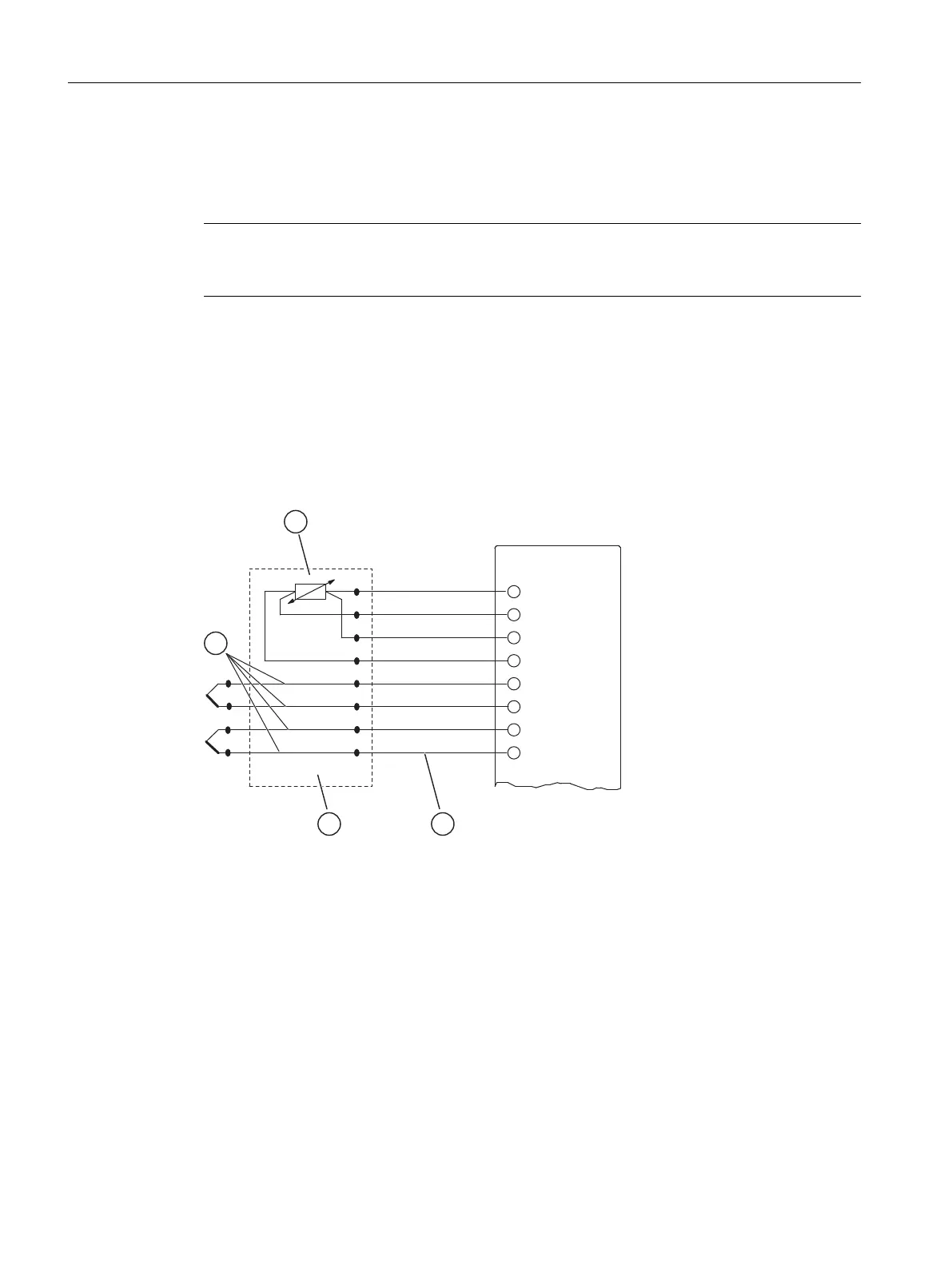
Connecting thermocouples using resistance thermometers
Connect the resistance thermometer to channel 0 of the module. Make sure that you configure
the "RTD on Channel 0" reference junction in STEP 7 for each channel that has a thermocouple
connected to it.
If all thermocouples connected to the module's inputs share a common reference junction,
compensate the circuit as follows:
M
+
: Measuring line (positive)
M
-
: Measuring line (negative)
I
C+
: Constant current line (negative)
I
C+
: Constant current line (negative)
(1) Compensating leads (same material as thermocouple)
(2) RTD on Channel 0
(3) Incoming line (Cu)
(4) Reference junction
Figure 5-17 Connection of thermocouples of the same type with external compensation by means of
a resistance thermometer, connected to channel 0
Analog modules
5.13 Connecting thermocouples
S7-400 Automation System Module Data
218 Reference Manual, Ausgabe 11/2016, A5E00850736-08

 Loading...


