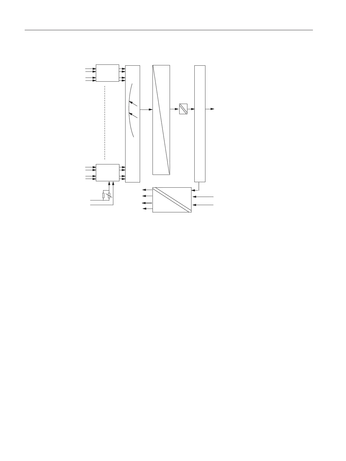
Circuit diagram for SM 431; AI 8 x 14 bit
24 V
0V
0V
- 15V
+ 5V
+ 15V
ENABLE
CH0
CH1
CH6
CH7
L+
M
A
D
OPTO RELAY
Measuring
range
module 0
Bus control
Measuring
range
module 3
MULTIPLEXER
Bus S7-400
Bus S7-400
Bus S7-400
Figure 5-24 Circuit diagram for SM 431; AI 8 x 14 bit
Analog modules
5.20 Analog input module SM 431; AI 8 x 14 Bit (6ES7431-1KF10-0AB0)
S7-400 Automation System Module Data
238 Reference Manual, Ausgabe 11/2016, A5E00850736-08

 Loading...


