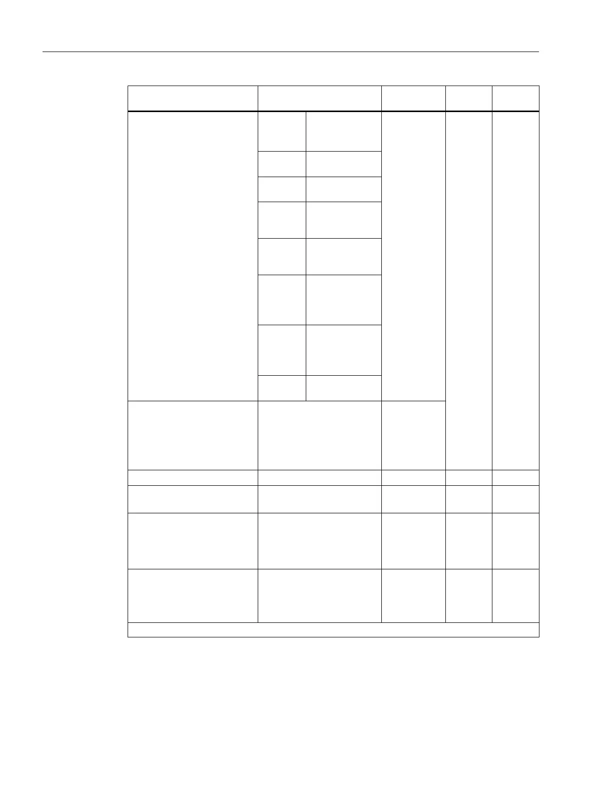
Parameters Value range Default set‐
ting
1
Parame‐
ter type
Scope
● Measuring method
Deactiva‐
ted
U
Voltage
U Static Channel
4DMU Current (4-wire
sensor)
2DMU Current (2-wire
sensor)
R-4L Resistance (4-
conductor con‐
nection)
R-3L Resistance (3-
conductor con‐
nection)
RTD-4L Thermal resistor
(linear, 4-con‐
ductor connec‐
tion)
RTD-3L Thermal resistor
(linear, 3-con‐
ductor connec‐
tion)
TC-L Thermocouple
(linear)
● Measuring range
For information on configura‐
ble measuring ranges of in‐
put channels, refer to the
chapter "Measuring methods
and measuring ranges of SM
431; AI 8 x 14 Bit".
± 10 V
● Reference temperature
- 273.15 to 327.67
o
C 0,00
o
C Dynamic Module
● Interference frequency
suppression
60 Hz; 50 Hz 50 Hz Static Channel
● Smoothing
None
Weak
Medium
Strong
None Static Channel
● Reference junction
None
RTD on Channel 0
Reference temperature val‐
ue dynamic
None
1
Only in the CR (central rack) is it possible to start up the analog modules with the default settings.
Measured value smoothing
You will find information that is generally applicable to the smoothing of analog values in the
respective section.
Analog modules
5.20 Analog input module SM 431; AI 8 x 14 Bit (6ES7431-1KF10-0AB0)
S7-400 Automation System Module Data
248 Reference Manual, Ausgabe 11/2016, A5E00850736-08

 Loading...


