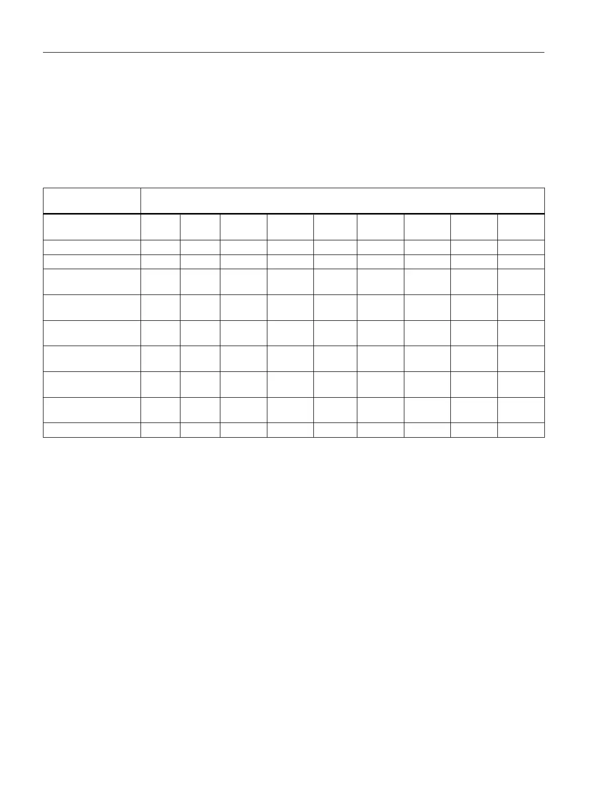
Circuit variants for the channels
Two channels are set in each case with the measuring range module. There are therefore
restrictions as regards the measuring method for the adjacent channels 0/1, 2/3, 4/5 and 6/7,
as shown in the following table:
Table 5-49 Selection of the measuring method for channel n and channel n+1 of the SM 431; AI 8 x 14 Bit
(6ES7431-1KF10-0AB0)
Measuring method,
channel n
Measuring method, channel n + 1
Deacti‐
vated
Voltage Current
4-DMU
Current
2-DMU
R-4L R-3L RTD-4L RTD-3L TC-L
Disabled x x x x x
Voltage x x x
Current 4-wire trans‐
ducer
x x
Current 2-wire trans‐
ducer
x x
4-wire
resistor
x
3-wire
resistor
x
Four-wire thermal re‐
sistor
x
3-wire thermal
resistor
x
Thermocouples x x x
Example
If you select "current (2-wire transducer)" for channel 6, you can only disable the measuring
method or set "current (2-wire transducer)" for channel 7.
Analog modules
5.20 Analog input module SM 431; AI 8 x 14 Bit (6ES7431-1KF10-0AB0)
S7-400 Automation System Module Data
250 Reference Manual, Ausgabe 11/2016, A5E00850736-08

 Loading...


