● Resolution 14 bits
● Supply voltage: 24 V DC only required for connection of 2-wire transducers
● Analog section isolated from the CPU
● Maximum permitted common mode voltage between the channels or between the reference
potentials of the connected sensors and M
ANA
8 V AC
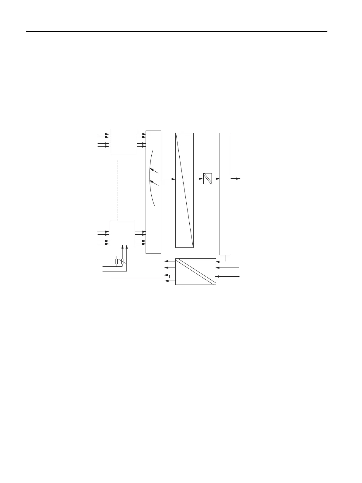
Circuit diagram for SM 431; AI 8 x 14 bit
CH0
CH1
CH6
CH7
+5V
0V
0V
- 15V
+ 5V
+ 15V
L+
M
ENABLE
A
D
MANA
MANA
Measuring
range
module 0
Measuring
range
module 3
MULTIPLEXER
Bus control
Bus S7-400
Bus S7-400
Bus S7-400
Figure 5-27 Circuit diagram for SM 431; AI 8 x 14 bit
Analog modules
5.21 Analog input module SM 431; AI 8 x 14 Bit (6ES7431-1KF20-0AB0)
S7-400 Automation System Module Data
254 Reference Manual, Ausgabe 11/2016, A5E00850736-08

 Loading...


