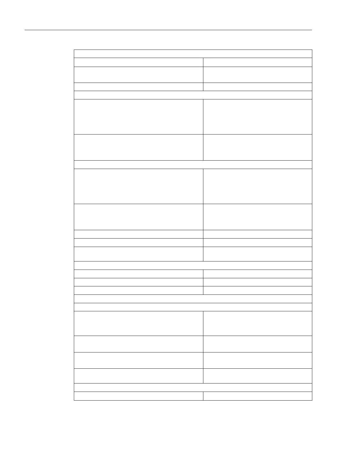
Interference voltage suppression for f = nx (f1 ±1%), (f1 = interference frequency) n = 1, 2 , ...
● Common mode interference (UCM < 2 V)
> 86 dB
● Series-mode interference (peak value of fault <
rated value of input range)
> 60 dB
Crosstalk between the inputs > 50 dB
Operational limit (throughout temperature range, relative to input range)
● Voltage input
– ± 1 V
– ± 10 V
– 1 to 5 V
± 0.65%
± 0.65%
± 1%
● Current input
– ± 20 mA
– 4 to 20 mA
± 0.65%
± 0.65%
Basic error limit (operational limit at 25°C, relative to input range)
● Voltage input
– ± 1 V
– ± 10 V
– 1 to 5 V
± 0.25%
± 0.25%
± 0.5%
● Current input
– ± 20 mA
– 4 to 20 mA
± 0.25%
± 0.25%
Temperature error (relative to input range) ± 0.01 % / K
Linearity error (relative to input range) ± 0.05%
Repeat accuracy (in settled state at 25°C, relative to
input range)
± 0.01%
Status, interrupts, diagnostics
Interrupts None
Diagnostic functions None
Substitute values can be connected No
Data for selecting a sensor
Input ranges (rated values)/input resistance
● Voltage
± 1 V / 10 MΩ
± 10 V / 100 MΩ
1 to 5 V / 100 MΩ
● Current
± 20 mA / 50 Ω
4 to 20 mA / 50 Ω
Permissible input voltage for voltage input (destruction
limit)
20 V continuous;
75 V for 1 ms (cycle clock ratio 1 : 20)
Permissible input current for current input (destruction
limit)
40 mA
Sensor connection
● For voltage measurement
Possible
Analog modules
5.22 Analog input module SM 431; AI 16 x 13 Bit (6ES7431-0HH00-0AB0)
S7-400 Automation System Module Data
268 Reference Manual, Ausgabe 11/2016, A5E00850736-08

 Loading...


