Measuring ranges
You set the measuring ranges by means of the measuring range modules on the module and
the "Measuring type" parameter in STEP 7.
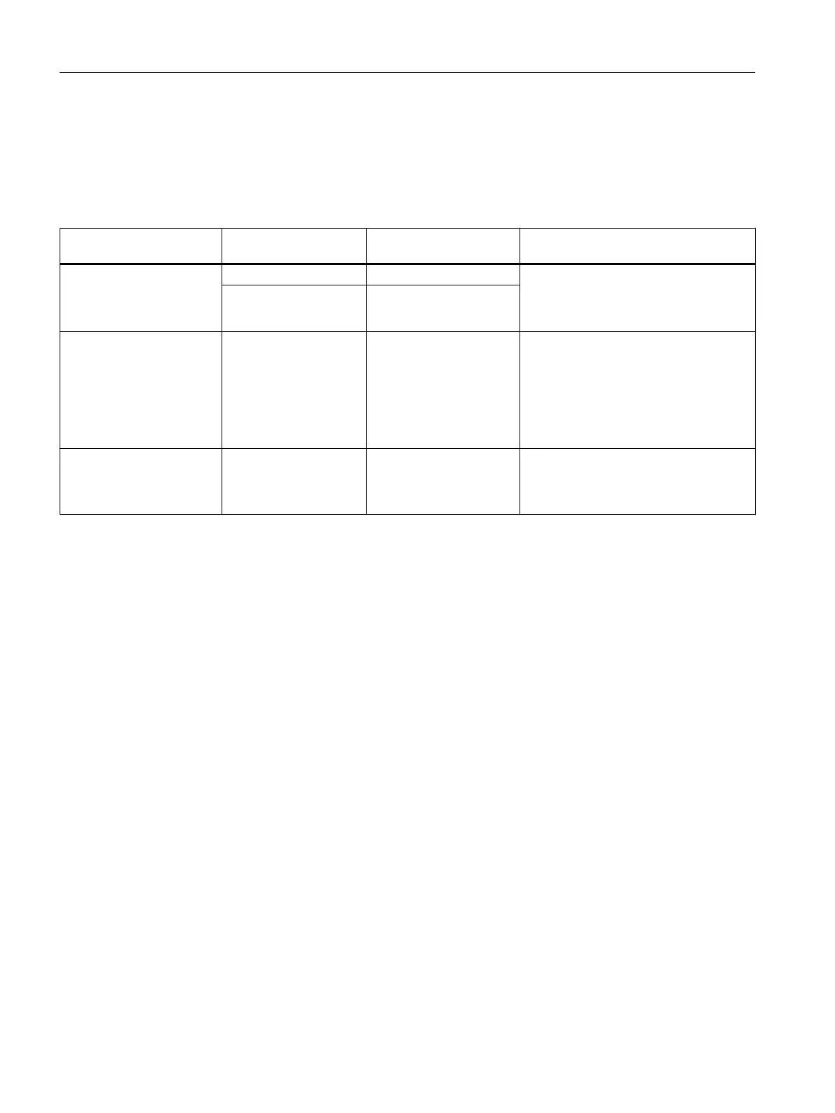
Table 5-60 Measuring ranges of the SM 431; AI 16 x 13 Bit
Selected measuring meth‐
od
Measuring range
(type of sensor)
Measuring range module
settings
Description
V: Voltage ±1 V A The digitized analog values are listed in
the section "Representation of analog
values for analog input channels" in the
voltage measuring range.
1 to 5 V
± 10 V
B
2DMU: Current (2-wire sen‐
sor)
4 to 20 mA D To supply these transducers with current
you must connect 24 V to the L+ and M
front connector terminals.
The digitized analog values are listed in
the section "Representation of analog
values for analog input channels" in the
current measuring range.
4DMU: Current (4-wire sen‐
sor)
4 to 20 mA
± 20 mA
C The digitized analog values are listed in
the section "Representation of analog
values for analog input channels" in the
current measuring range.
Default
The module has the following default settings in
STEP 7
:
● Measuring method "voltage"
● Measuring range "± 10 V".
You can use this combination of measuring method and measuring range without configuring
the SM 431; AI 16 x 13 Bit in
STEP 7
.
See also
Representation of analog values of analog input channels (Page 169)
Analog modules
5.22 Analog input module SM 431; AI 16 x 13 Bit (6ES7431-0HH00-0AB0)
S7-400 Automation System Module Data
272 Reference Manual, Ausgabe 11/2016, A5E00850736-08

 Loading...


