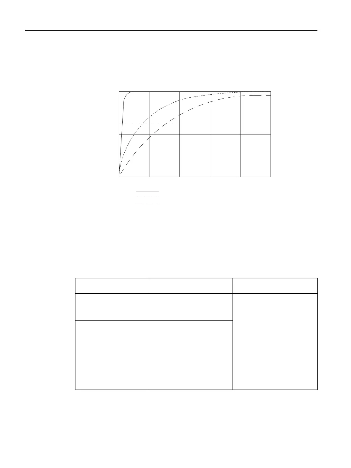
The following figure shows for the module the number of module cycles, in the case of a step
response, after which the smoothed analog value is applied to almost 100%, depending on
the smoothing setting. The figure applies to every change of signal at an analog input.
50
100
0
63
60 8020 10040
Signal variation in
percent
Step response for any analog input signal
Smoothing Low:
average:
high:
Module cycles
Figure 5-34 Step response of the SM 431; AI 16 x 16 Bit (6ES7431-7QH00-0AB0)
Displaying parameter assignment errors
The SM 431; AI 16 x 16 Bit has diagnostics capability. Below you will find an overview of the
displays that are possible for modules with parameter assignment errors.
Table 5-62 Diagnostic information of the SM 431; AI 16 x 16 Bit
Incorrect parameter assign‐
ment
Possible display Explanation
Of the module
● Module error
● Internal error
● Incorrect parameters
You will find explanations of the di‐
agnostics information in the re‐
spective tables.
Affecting certain channels
● Module error
● Internal error
● Channel error
● Incorrect parameters
● Channel information available
● Channel error vector
● Channel parameter
assignment error
Analog modules
5.23 Analog input module SM 431; AI 16 x 16 Bit (6ES7431-7QH00-0AB0)
S7-400 Automation System Module Data
286 Reference Manual, Ausgabe 11/2016, A5E00850736-08

 Loading...


