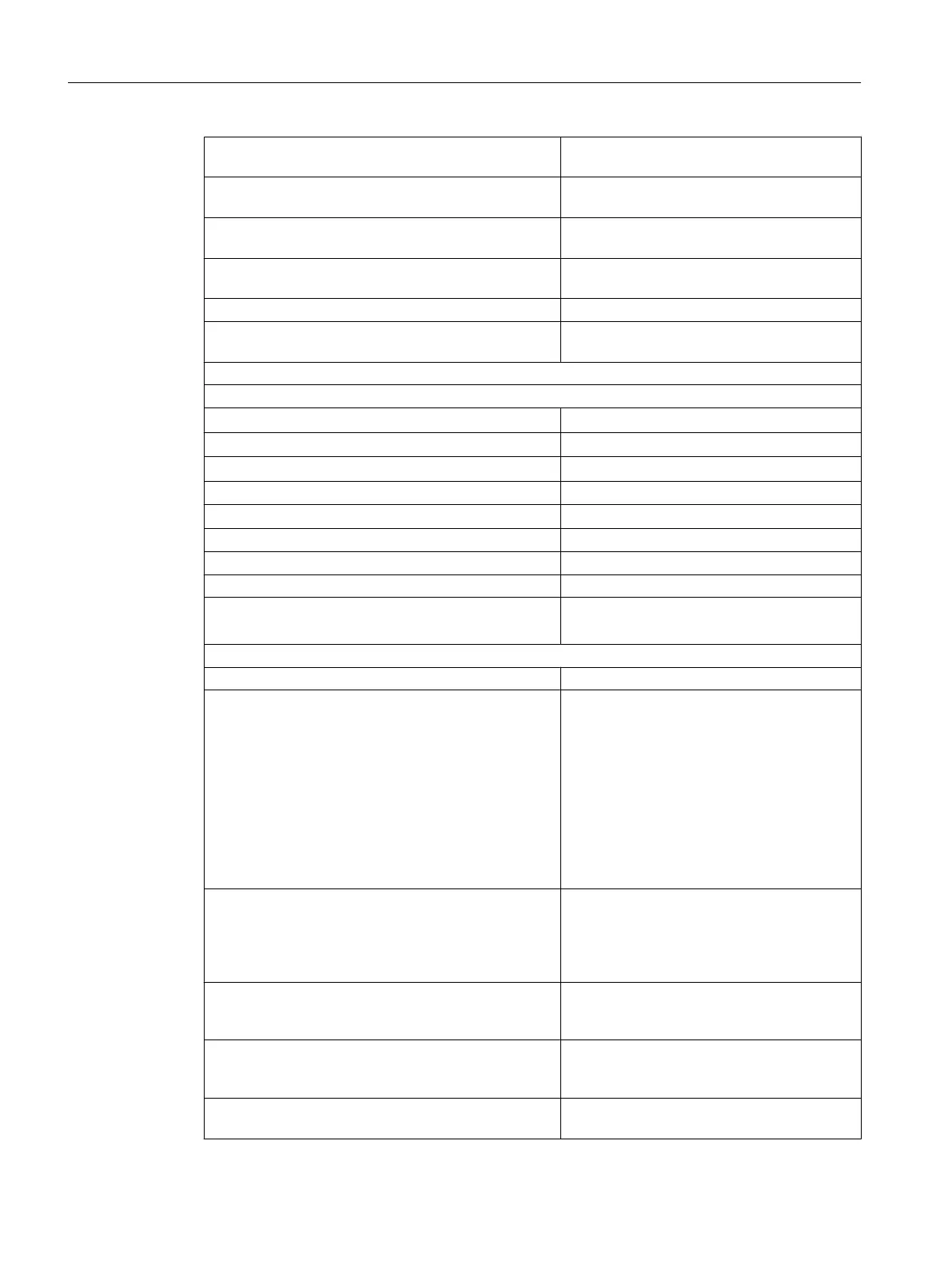
Type B
400 °C to 1820 °C
± 2.2 °C
Linearity error (relative to input range) Additional error
± 0.05%
Repeat accuracy (in settled state at 25°C, relative to
input range)
Additional error
± 0.05%
Connection for compensation of cold connection point 6ES7431-7KF00-
6AA0
Operational limit
● Internal temperature compensation error
Additional error
± 2.0%
Status, interrupts, diagnostics
Interrupts
● Hardware interrupt
Configurable
● Hardware interrupt when limit value exceeded
Configurable
● Diagnostic interrupt
Configurable
Diagnostic functions Configurable
● Group fault display
Configurable
For internal fault Red LED (INTF)
For external fault Red LED (EXTF)
Diagnostic information can be read out Possible
Monitoring for
● wire break
Data for selecting a sensor
Input range (rated values) / input resistance
● Voltage
± 25 mV > 2 MΩ
± 50 mV > 2 MΩ
± 80 mV > 2 MΩ
± 100 mV > 2 MΩ
± 250 mV > 2 MΩ
± 500 mV > 2 MΩ
± 1 V > 2 MΩ
± 2.5 V > 2 MΩ
± 5 V > 2 MΩ
+ 1 to 5 V > 2 MΩ
± 10 V > 2 MΩ
● Current
± 20 mA 50 Ω
+ 4 to 20 mA 50 Ω
± 10 mA 50 Ω
± 5 mA 50 Ω
± 3,2 mA 50 Ω
● Thermocouple
Types B, N, > 2 MΩ
E, R, S, J, L,
T, K, U
Maximum input voltage
for voltage input (destruction limit)
35 V continuous;
75 V for max. 1 s
(duty factor 1:20)
Maximum input current for current input (destruction
limit)
32 mA
Analog modules
5.25 Analog input module SM 431; AI 8 x 16 Bit (6ES7431-7KF00-0AB0)
S7-400 Automation System Module Data
308 Reference Manual, Ausgabe 11/2016, A5E00850736-08

 Loading...


