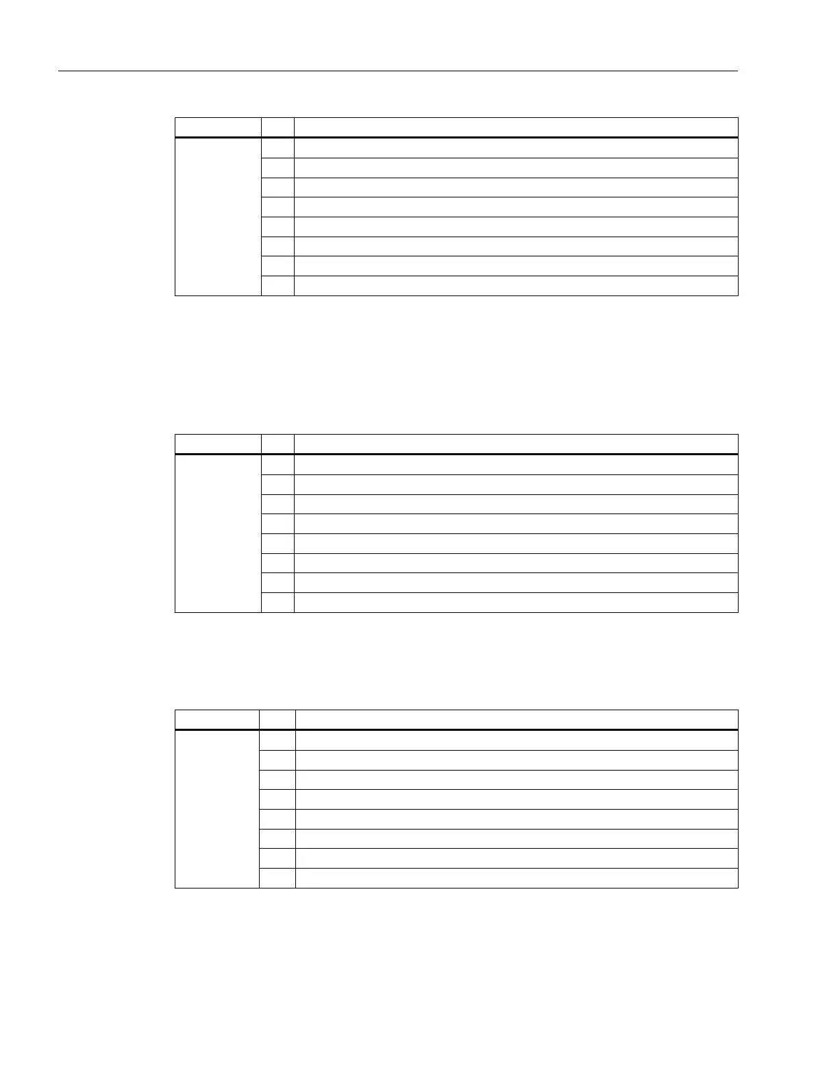
Byte Bit Meaning
Byte 8 7 Channel error 15
6 Channel error 14
5 ...
4 ...
3 ...
2 ...
1 Channel error 9
0 Channel error 8
Bytes 9 and 24 of the SM 421; DO 16 x DC 20-125 V/1.5 A
Data record 1 contains the channel-specific diagnostic data, starting at bytes 9 to 24. The figure
below shows the assignment of the diagnostic byte for a channel of the module.
Table B-11 Diagnostic byte for a channel of the SM 422; DO 16 x DC 20-125 V/1.5 A
Byte Bit Meaning
Bytes 9 - 24 7 0
6 External load voltage missing
5 0
4 0
3 Short-circuit to M
2 0
1 0
0 Configuring/parameter assignment error
Bytes 2 and 3 of the SM 422; DO 32 x DC 24 V/0.5 A
Table B-12 Bytes 2 and 3 of the diagnostic data of the SM 422; DO 32 x DC 24 V/0.5 A
Byte Bit Meaning
Byte 2 7 0
6 0
5 0
4 Module-internal supply voltage failure
3 0
2 Operating mode 0: RUN; 1: STOP
1 0
0 0
Diagnostic data of signal modules
B.4 Diagnostic data of the digital output modules as of byte 2
S7-400 Automation System Module Data
414 Reference Manual, Ausgabe 11/2016, A5E00850736-08

 Loading...


