BAF lights up if the backup voltage on the backplane bus is too low. Possible causes of this
include:
● Battery (batteries) empty or battery polarity has been reversed.
● External supply via CPU or receive IM is defective or supply from secondary power supply
module is defective or missing.
● Short-circuit or overload on the battery voltage.
Note
Due to internal capacities, if you remove the battery or switch off the external supply, some
time may elapse before BAF, BATT1F, or BATT2F lights up.
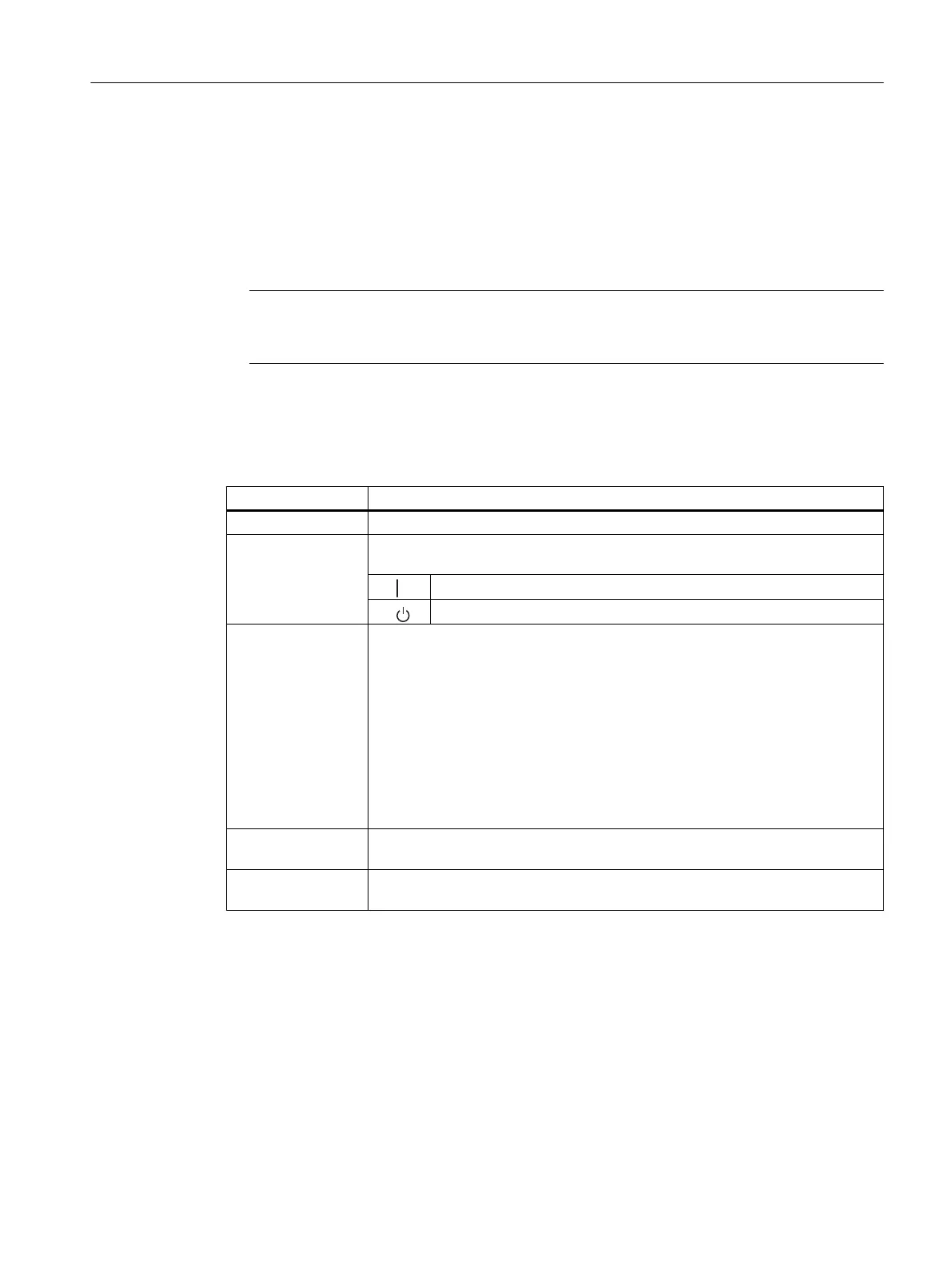
Function of the operator controls of the power supply modules
Table 3-5 Function of the operator controls of the power supply modules
Control Function
FMR button For acknowledging and resetting a fault indicator after correcting the fault
Standby switch Switches the output voltages (5 V VDC24 VDC) to 0 V by intervening in the
control loop (no mains disconnection).
●
Output voltages at nominal value
●
Output voltage 0 V
Switches
BATT.INDIC
Used for setting LEDs and battery monitoring
Where one battery can be used (PS 407 4A, PS 405 4A):
● OFF: LEDs and monitor signals inactive
● BATT: BAF/BATTF LEDs and monitor signals active
Where two batteries can be used (PS 407 10A, PS 407 20A, PS 405 10A, PS
405 20A):
● OFF: LEDs and monitor signals inactive
● 1 BATT: Only BAF/BATT1F LEDs (for battery 1) active.
● 2 BATT: BAF/BATT1F/BATT2F LEDs (for batteries 1 and 2) active.
Battery compart‐
ment
For backup battery (batteries)
Power connection 3-pin connector for the power main
(do not pull and plug under power)
Cover
The battery compartment, battery selector switch, voltage selector switch and power
connection are housed under one cover. The cover must remain closed during operation in
order to protect these operator controls and to prevent static electricity from affecting the
battery connections.
Discharge your body before you start taking any measurements on a module. Do so by
touching grounded metallic parts. Always use grounded measuring instruments.
Power supply modules
3.4 Operator controls and indicators
S7-400 Automation System Module Data
Reference Manual, Ausgabe 11/2016, A5E00850736-08 47

 Loading...


