INTF, 5 VDC, 24 VDC LEDs
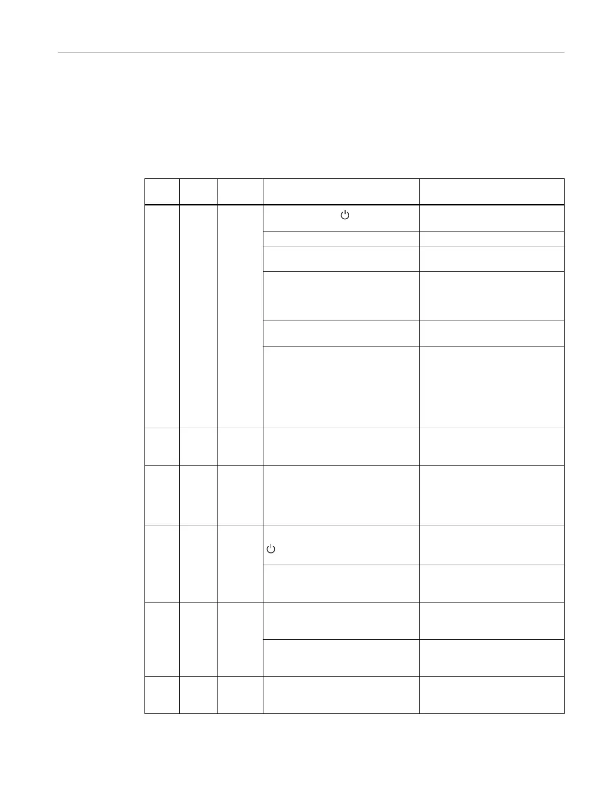
The following table shows the faults indicated by the INTF, 5 VDC, and 24 VDC LEDs and lists
how to remedy the faults. The status of the BAF, BATTF, BATT1F, and BATT2F LEDs is not
relevant here.
Table 3-7 INTF, 5 VDC, 24 VDC LEDs
INTF
LED
LED
DC5V
LED
DC24V
Cause of fault Remedy
D D D Standby switch in position Set standby switch to the | posi‐
tion
Line voltage missing Check line voltage
Internal fault, power supply module
defective
Replace power supply module
Cutoff after overvoltage on 5 V or
non-permissible external supply
Disconnect from mains and recon‐
nect after approximately 3 mi‐
nutes; if necessary, remove exter‐
nal supply
Power supply module operated in
wrong slot
Install the power supply module in
the correct slot (slot 1)
Short-circuit or overload on 5 V Switch off the power supply mod‐
ule, remove the source of the
short-circuit; after approximately 3
seconds, the power supply mod‐
ule can be switched on with the
standby switch or via the power
system.*
D H D Overvoltage on 24 V Check if there is an external sup‐
ply; if not, replace power supply
module.
H D* D Short-circuit or overload on 5 V and
24 V and overheating
Check the load on the power sup‐
ply module. Remove module if
necessary. Wait 5 minutes before
switching the power supply mod‐
ule again.
H H D If the standby switch is set to the
position, illegal external supply on
5 V
Remove all modules; determine
which module is faulty.
If the standby switch is set to the |
position, short-circuit or overload on
24 V.
Check the load on the power sup‐
ply module. Remove module if
necessary.
D B H Voltage restored after short-circuit or
overload on 5 V if faults occur in op‐
eration
Press FMR button: Flashing
changes to steady light
Dynamic overload on 5 V Check load on the power supply
module. Possibly remove mod‐
ules.
D B B Voltage restored after short-circuit or
overload on 5 V and 24 V if faults oc‐
cur in operation
Press FMR button: Flashing
changes to steady light
Power supply modules
3.5 Fault/Error messages via LEDs
S7-400 Automation System Module Data
Reference Manual, Ausgabe 11/2016, A5E00850736-08 49

 Loading...


