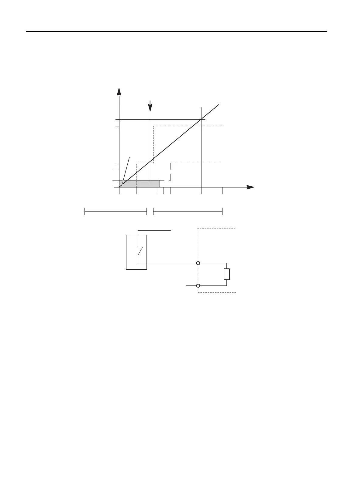
Input characteristic curve for digital inputs
As long as the current flowing into the module remains ≤ 1.5 mA, the module recognizes this
as a "0" signal.
0,5
1,5
2
6
7
0 5 11 13 15 24 30 L+ (V)
- 30 V
I E (mA)
“0” “1”
1
0
L+
M
I < 1,5 mA
Typ. switching threshold(9.5 V)
Resistance characteristic curve
I min to IEC 61131; type 2
BERO
standard
I < 1,5 mA
PLC input resistance
--> “0” Signal
2-wire BERO
I min to IEC 61131; type 1
Figure 4-1 Input characteristic curve for digital inputs
Digital modules
4.6 Input characteristic curve for digital inputs
S7-400 Automation System Module Data
96 Reference Manual, Ausgabe 11/2016, A5E00850736-08

 Loading...


