DC connection
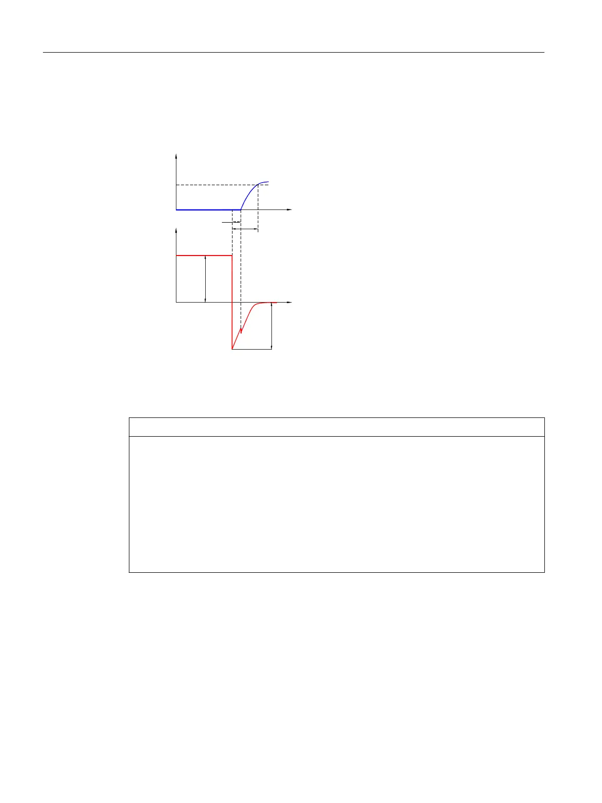
The basic curve of the voltage when the excitation winding (coil) (1.2) is switched o is as
follows.
W
W
0
8
;0
8%
89PD[
W
W
0
U
B
Operating voltage (coil voltage)
U Transient voltage
Figure5-8 Basic curve of the voltage when turning o the excitation winding
NOTICE
Overvoltages when switching o
The voltage peak U
Vmax
when switching o can reach several 1000 V in the millisecond range
without a protective circuit.
The excitation winding (coil) (1.2), switching contacts and electronic components can be
destroyed.
Sparks form at the switch on switch-o.
• When it is switched o, the current must therefore be reduced via a snubber circuit. This also
limits the voltages. The maximum permissible overvoltage when switching o must not
exceed 1500V.
If Kendrion Binder rectiers are used, the protective circuit for the internal electronic
components and for the excitation winding (coil) (1.2) is integrated. This does not apply
Motor components and options
5.2Options
1PH8 SIMOTICS M main motors
190 Conguration Manual, 12/2022, A5E51895839A

 Loading...


